Introduction:
The Importance of Optimized Design in Plastic Injection Molding
Optimizing plastic part design for injection molding is a crucial step for any plastic parts manufacturer looking to improve efficiency, reduce costs, and ensure high-quality results. The injection molding process, which involves melting plastic and injecting it into a custom-designed mold, is widely used to create durable, consistent parts at scale. However, without thoughtful design, manufacturers may face issues like material waste, long cycle times, and increased production costs. By focusing on design elements that support efficient molding, manufacturers can maximize the productivity and sustainability of their operations.
Design optimization doesn’t just impact the mold’s functionality; it affects every stage of production, from material choice to cooling time and ejection. Whether you’re creating custom plastic parts or high-volume production pieces, designing with efficiency in mind leads to faster production cycles, lower costs, and fewer defects. This guide explores how to optimize plastic part design for injection molding, diving into principles, materials, structural considerations, and techniques to create parts that are both functional and manufacturable.
Key Principles of Plastic Part Design for Injection Molding
To effectively optimize plastic part design for injection molding, it’s essential to understand a few core principles that support efficient production and high-quality results. These principles help balance functionality, manufacturability, and cost-effectiveness, which are vital for mass production as well as for custom parts. Let’s explore the foundational aspects of injection molding design.
Understanding Mold Flow
Mold flow refers to how molten plastic moves through the mold cavity during injection. Efficient mold flow is critical for avoiding common molding issues like incomplete filling, air entrapment, and uneven cooling, all of which can compromise part quality. In an optimized design, flow paths are as short and uniform as possible, reducing the risk of turbulence or stagnation. Using computer-aided simulations (such as mold flow analysis) during the design phase can help predict how the material will fill the mold and allow designers to make necessary adjustments to ensure even distribution of plastic.
Design for Manufacturability (DFM)
DFM is a critical approach that considers the ease of manufacturing throughout the design process. For injection molding, DFM principles help designers create parts that minimize production time, cost, and waste. This may involve choosing materials that flow smoothly through the mold, designing with consistent wall thicknesses to avoid defects, and ensuring that complex features do not complicate the molding process. By emphasizing DFM, designers can ensure that parts are not only functional but also practical and cost-efficient to produce.
Balance Between Functionality and Manufacturability
While functionality is essential, it’s equally important to ensure that design features do not add unnecessary complexity to the mold. For example, a designer might need to avoid intricate undercuts or non-essential thin-walled sections that complicate production. Features that are critical to the part’s function should be carefully considered for how they might affect manufacturing; if a feature can be simplified without sacrificing performance, it should be. Balancing these factors ensures that the part performs its intended role while remaining feasible for high-volume production.
Material Selection and Its Influence on Design
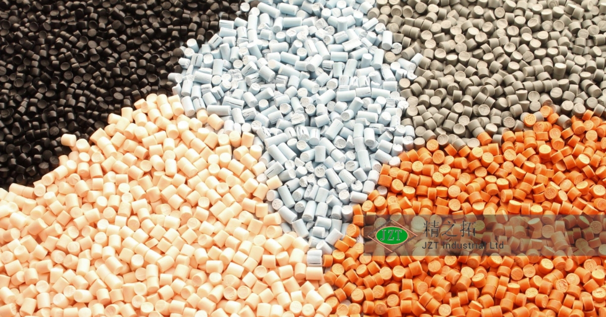
Material selection directly affects the design choices for an injection-molded part, as different plastics have unique properties like shrinkage, melt flow, and cooling rates. The chosen material must align with the part’s functional requirements, such as durability or flexibility, while also being compatible with the mold design. For example, a high-shrinkage material may require adjustments in part dimensions to achieve accurate final dimensions. Ensuring that material properties are considered early in the design process helps prevent costly redesigns or production issues down the line.
Choosing the Right Material for Injection Molding
Selecting the appropriate material is a foundational step in optimizing design for injection molding. The material chosen impacts factors such as durability, flexibility, resistance to temperature and chemicals, and overall manufacturability. Here’s a breakdown of the considerations when choosing materials for plastic injection molds.
Common Materials and Their Characteristics
Certain plastics are especially popular in injection molding due to their balance of durability, cost, and versatility. Here are some commonly used materials:
- ABS (Acrylonitrile Butadiene Styrene): Known for its impact resistance and durability, ABS is ideal for parts that require toughness, like enclosures and housings.
- Polypropylene (PP): Lightweight and resistant to chemicals, PP is often used in containers, medical components, and automotive parts.
- Polycarbonate (PC): With excellent transparency and impact resistance, PC is a great choice for clear parts or parts that need to withstand high impact.
- Nylon (PA): Known for its strength and high melting point, nylon is ideal for mechanical parts and components that require wear resistance.
Each material has unique characteristics that make it suitable for specific applications. Designers must weigh the material’s properties against the requirements of the part and the molding process to make the best choice.
Considerations for Material Selection
When choosing a material, consider several factors, including durability, flexibility, chemical resistance, and the part’s exposure to heat. Certain applications may prioritize aesthetics, like color or surface finish, while others require materials that can handle stress and temperature fluctuations. Material cost is also important—higher-quality materials may provide the desired characteristics but could impact the overall budget.
Impact of Material Properties on Design
Materials have properties like shrinkage rates, flow characteristics, and thermal expansion, all of which influence the design. For example, high-shrinkage materials require more precise adjustments to achieve the final dimensions, while materials with low flow rates might need simplified features or specific gate placements to ensure even filling. Understanding these properties helps designers make decisions that align with both part performance and manufacturability.
Environmental Considerations
Sustainability is increasingly a priority for manufacturers, and choosing eco-friendly materials, like recyclable or bio-based plastics, is an option worth exploring. Some manufacturers may consider using recycled plastic or bioplastics, depending on the part’s application and environmental impact goals. Using sustainable materials can enhance a brand’s appeal and align with regulatory requirements for environmentally responsible production.
Wall Thickness: A Key Element in Plastic Part Design
Wall thickness is one of the most critical factors in designing custom plastic parts for injection molding, as it directly affects cooling time, material usage, and part strength. Achieving the correct wall thickness helps prevent common defects like warping, sink marks, and uneven cooling, all of which can complicate production and compromise quality.
Why Uniform Wall Thickness is Essential
Maintaining a uniform wall thickness helps ensure consistent cooling throughout the part, which reduces the risk of defects and enhances structural integrity. When walls have uneven thickness, areas with thicker walls take longer to cool, leading to shrinkage and warping. By keeping walls consistent, designers improve the flow of plastic, leading to faster cooling times and more predictable results.
Recommended Wall Thicknesses for Different Plastics
Each type of plastic has an optimal range for wall thickness that balances strength and cooling time. For example:
- ABS: 1.5 to 4 mm
- Polypropylene: 0.8 to 3.8 mm
- Polycarbonate: 1 to 3.5 mm
Adhering to these recommended thicknesses helps ensure that parts cool properly and maintain their intended structural properties. Thinner walls can reduce material use and cycle time, but they must still be thick enough to prevent breakage or warping.
Challenges with Non-Uniform Walls
Non-uniform walls often lead to issues like sink marks and warping, as thicker sections cool more slowly than thinner sections. These defects not only impact the part’s appearance but can also affect its function, especially in applications requiring precise dimensions or a smooth finish. To avoid these problems, designers should aim to keep wall thickness consistent or use techniques like ribbing to reinforce areas that require additional strength.
Design Tips for Optimizing Wall Thickness
Achieving optimal wall thickness requires thoughtful design, including features like:
- Ribbing: Adding ribs to areas that require extra strength without increasing wall thickness.
- Coring: Removing unnecessary material from thick areas to maintain a uniform thickness.
- Gradual Transitions: Using gradual changes in thickness, instead of abrupt shifts, to allow for even cooling and reduced stress points.
By implementing these design techniques, manufacturers can improve part quality, reduce cycle times, and minimize material waste.
Designing for Strength and Structural Integrity
Injection-molded parts often need to withstand stress, impact, and wear, particularly in applications like automotive, medical, and consumer products. Optimizing for strength and integrity ensures that parts perform reliably without requiring excess material, which could increase costs.
Incorporating Ribs and Gussets
Ribs and gussets are essential for reinforcing parts without adding bulk. Ribs add strength by increasing stiffness in specific areas without significantly increasing material use. Gussets, which are supportive features added to corners or junctions, provide additional stability. However, designers must avoid placing ribs too close to part surfaces, as this can cause sink marks on the exterior.
Avoiding Stress Concentration Points
Sharp corners and sudden changes in thickness create stress concentration points that can lead to cracking or failure under load. Rounded corners and gradual transitions help distribute stress evenly throughout the part, minimizing the risk of fractures. Avoiding these high-stress areas is especially important for parts subjected to repeated stress or impact.
Considering Load-Bearing Requirements
When designing load-bearing parts, understanding how forces will be applied is essential for ensuring durability. For parts expected to endure heavy loads, materials with higher tensile strength should be used, and support features like ribs or additional wall thickness may be required. Careful consideration of load-bearing requirements helps ensure that parts maintain their structural integrity over time.
Use of Bosses for Fastening
Bosses are raised sections used for fasteners, such as screws, and must be designed carefully to avoid stress points. A properly designed boss distributes load evenly, preventing cracks around the fastener. Bosses should be sized and placed strategically to align with the part’s functional needs while minimizing material use and potential stress points.
By focusing on these structural elements, designers can create robust, durable parts that meet application requirements without excess material or complexity, supporting both efficiency and quality in injection molding.
Optimizing Part Geometry for Efficient Molding
Geometry plays a significant role in how efficiently a part can be molded. Complex shapes may be necessary to meet functional requirements but can complicate the molding process. By simplifying geometry where possible, manufacturers can achieve faster cycle times, reduce waste, and enhance part consistency.
Rounded Corners and Fillets
Sharp corners cause uneven flow, creating turbulence that leads to incomplete filling, stress points, and cooling issues. Rounded corners, or fillets, promote smoother flow, making it easier to fill the mold without trapping air or causing defects. Fillets also reduce stress concentrations, enhancing part durability and reducing the risk of cracking.
Draft Angles and Ejection
Draft angles are essential for ensuring that parts can be ejected smoothly from the mold. Without a slight taper (typically between 1-3 degrees), parts may stick to the mold, causing defects or damage. Proper draft angles minimize ejection force, making the process faster and preventing unnecessary wear on the mold.
Avoiding Under-Cuts and Complex Features
Undercuts create challenges for mold ejection, often requiring complex tooling solutions or secondary operations that increase production costs. If undercuts are unavoidable, designers can use side actions or lifters in the mold, though this adds complexity. Where possible, parts should be simplified to avoid these features, balancing functionality with manufacturability.
Designing for Symmetry
Symmetry in part design simplifies the molding process and minimizes warping. Parts with symmetrical designs distribute cooling evenly, preventing deformation as they solidify. When asymmetry is necessary, designers should account for potential cooling imbalances and adjust cooling systems accordingly.
By considering these aspects of geometry, manufacturers can create parts that are easy to produce, reducing cycle times and improving overall production efficiency.
Gate Location and Design in Injection Molding
Gate placement is a critical aspect of plastic injection molds as it directly influences the flow of molten plastic into the mold, the appearance of the final product, and the part’s structural integrity. Proper gate design and location ensure that the material fills the mold cavity efficiently, avoiding defects like flow lines, sink marks, or air traps, and ensuring the aesthetic quality of the finished part.
Importance of Gate Placement
The position of the gate determines the flow path of the molten plastic, which affects how the mold is filled. A well-placed gate allows for even flow distribution, reducing the risk of warping and incomplete fills. Improper gate location can result in defects like weld lines, where flows of material converge, or excessive cooling, which can cause weak spots. In some cases, a gate that is too close to a part’s critical feature may create blemishes or weaken the structure. Therefore, gate placement should be carefully planned to ensure smooth, efficient filling and to maintain the integrity of custom plastic parts.
Types of Gates
Several types of gates are used in injection molding, each suited to different applications:
- Edge Gate: Commonly used for flat parts, edge gates allow the material to flow in from the side. They are ideal for large, simple parts but may leave marks along the parting line.
- Hot Tip Gate: This type of gate delivers material directly to the center of the part through a heated nozzle, providing excellent surface finish and minimizing marks.
- Pin Gate: Often used in multi-cavity molds, pin gates help deliver material to small, precise areas and are ideal for complex parts.
- Submarine or Tunnel Gate: This gate type is hidden, allowing it to automatically separate from the part during ejection, reducing the need for manual trimming.
Selecting the appropriate gate type depends on the part’s geometry, material, and aesthetic requirements.
Gate Sizing and Cooling Considerations
The size of the gate impacts the pressure and flow rate of the injected material. A larger gate allows for faster flow, but it can also leave a more noticeable mark. A smaller gate requires more pressure and can prolong cycle time but results in a cleaner finish. It’s crucial to balance gate size to optimize both the flow rate and the cooling process, as this helps ensure a uniform cooling cycle and reduces defects.
Gate Removal and Finish
After the part is ejected, gates often leave a small mark or vestige that may need to be trimmed for aesthetic purposes. Planning for easy gate removal and ensuring that the location of the gate will not impact the visible areas of the part can help maintain a clean finish. Designing parts with gate vestiges in non-visible areas, or using gates that break away cleanly, can streamline post-processing and improve the overall appearance of the finished product.
Designing for Efficient Cooling
Cooling is a critical stage in injection molding, as it directly affects cycle time and the quality of the final product. Optimizing cooling through thoughtful design reduces production time, minimizes warping, and ensures that custom plastic parts meet tight tolerances.
Importance of Cooling Channels
Cooling channels are pathways built into the mold to allow coolant (usually water) to flow through and absorb heat from the molten plastic. The faster and more evenly a part cools, the more dimensionally stable and defect-free it will be. Efficient cooling channels help maintain uniform temperatures throughout the mold, which is essential for reducing cycle times and improving part consistency.
Optimal Cooling Channel Placement
The placement of cooling channels should align closely with the part’s geometry to ensure that heat is removed uniformly. Cooling channels positioned too far from thick sections of the part can lead to uneven cooling, resulting in warping or shrinkage. Using 3D modeling and simulation tools can help visualize heat distribution and adjust cooling channel designs accordingly to achieve optimal heat removal.
Advanced Cooling Techniques
New technologies like conformal cooling provide advanced solutions for complex part geometries. Conformal cooling uses 3D printing or advanced manufacturing techniques to create cooling channels that conform to the shape of the mold cavity. This allows for more precise and effective cooling, particularly for intricate or irregular parts that standard straight-line cooling channels cannot adequately address. Conformal cooling can significantly reduce cycle times and improve the overall quality of parts by preventing hotspots.
Avoiding Hot Spots in the Mold
Hot spots, or areas where heat accumulates, can cause defects like warping, sink marks, or even stress fractures. Designing parts and molds to minimize variations in wall thickness helps avoid hotspots by allowing heat to dissipate evenly. Additionally, placing cooling channels close to these areas or using heat sinks can help address localized heating, improving the part’s dimensional accuracy and surface finish.
Minimizing Sink Marks and Warping
Sink marks and warping are common issues in injection molding that can compromise the aesthetic and functional qualities of plastic parts. These defects often result from improper cooling or uneven material flow, making it essential to address them during the design phase.
Understanding Sink Marks and Their Causes
Sink marks are depressions or dimples on the surface of a part, usually occurring in areas where the wall thickness is inconsistent. As thicker sections cool and shrink, the surface may contract inward, creating visible imperfections. Sink marks can be particularly problematic for parts with cosmetic requirements or those that need a smooth finish for functional purposes.
Design Techniques to Minimize Sink Marks
To reduce the occurrence of sink marks, designers should strive for consistent wall thickness throughout the part. Features like ribs can help reinforce thick sections without adding mass, which can otherwise lead to shrinkage issues. Adjusting the gate location can also improve the material flow and pressure distribution, helping fill thicker areas more evenly and minimizing shrinkage.
Preventing Warping
Warping occurs when parts cool unevenly, causing them to distort or bend. This can make assembly difficult and affect the performance of plastic injection molds designed for precise fits. Designing for uniform cooling is key to preventing warping, including incorporating features like draft angles and ensuring symmetrical part design. Material choice also plays a role—materials with high shrinkage rates require special attention to cooling strategies.
Material Shrinkage and Its Impact on Design
All plastics shrink as they cool, but the rate of shrinkage varies by material. Shrinkage must be accounted for in the mold design to ensure that the final part dimensions are accurate. Using simulation software to predict shrinkage can help designers make adjustments before production begins, reducing the risk of defects and costly iterations.
Reducing Cycle Time Through Design Optimization
Cycle time is a key factor in determining the overall efficiency of the injection molding process. Shorter cycles lead to increased production rates and lower costs per part, making cycle time optimization crucial for high-volume production.
Designing for Shorter Cycle Times
Design elements like consistent wall thickness and optimized cooling channel placement can significantly reduce cooling time, which is the longest phase of the injection molding cycle. Additionally, designing with fewer complex features that require extended mold filling or ejection times helps streamline the process.
Mold Design Considerations for Efficiency
Multi-cavity molds, which produce multiple parts in a single cycle, can dramatically improve production speed. However, this approach requires careful consideration of material flow and cooling to ensure consistency across cavities. Optimized runner systems, which deliver molten plastic to the mold cavities, help minimize waste and ensure that material is distributed quickly and evenly.
Balancing Aesthetics with Efficiency
In many cases, the visual appeal of a part must be balanced with efficient manufacturing. For example, textured surfaces or certain cosmetic features may require slower cycles to prevent defects like flow lines. Finding a balance between aesthetic requirements and efficient production is key to achieving both quality and speed.
Using Simulation Tools to Predict Cycle Times
Simulation software can predict how changes in design will affect cycle time, providing valuable insights before a mold is even manufactured. Mold flow analysis tools allow designers to test different gate locations, cooling channel placements, and material choices to identify the most efficient configurations. This helps reduce trial-and-error during production, saving time and costs.
Parting Line and Ejector Pin Placement
The location of the parting line and ejector pins affects both the manufacturability and aesthetics of an injection-molded part. These features must be carefully planned to ensure smooth production and minimize post-processing work.
What is a Parting Line and Why It’s Important
The parting line is where two halves of a mold meet, leaving a slight line on the molded part. Proper placement of the parting line ensures that it does not interfere with the part’s appearance or functionality. For parts where surface finish is critical, placing the parting line in a less visible area can improve the overall aesthetic.
Positioning Ejector Pins for Effective Ejection
Ejector pins push the finished part out of the mold once it has cooled. Placing ejector pins correctly ensures smooth ejection and minimizes the risk of distortion or damage. Ejector marks are often inevitable, but they can be placed in less visible areas of the part to maintain a clean appearance.
Minimizing Flashing and Imperfections
Flashing occurs when excess material leaks out between the mold halves, forming a thin edge around the part. Proper parting line placement and well-maintained molds can help reduce the occurrence of flash. Ensuring tight tolerances between mold halves and using the right clamping force are also crucial for preventing this issue.
Designing with the Ejection Process in Mind
Parts should be designed to facilitate easy ejection from the mold. This includes adding draft angles to prevent parts from sticking and ensuring that the ejector pins have sufficient surface area to distribute force evenly. By considering the ejection process early in the design phase, manufacturers can avoid delays and defects during production.
Using Simulation and Prototyping for Design Validation
Simulation tools and prototyping are invaluable for validating and refining part designs before committing to full-scale production. By testing designs virtually or with physical prototypes, manufacturers can identify and address potential issues early, saving time and costs.
Role of CAD and Simulation Software
Computer-aided design (CAD) and simulation software allow designers to model the injection molding process and predict how materials will behave. These tools provide insights into factors like material flow, cooling rates, and potential weak points, allowing designers to make adjustments before creating a physical mold.
Prototyping for Design Testing
Prototyping, whether through 3D printing or trial molds, provides a hands-on way to test design features and assess functionality. Rapid prototyping methods are cost-effective for small runs and can reveal practical issues that may not be apparent in simulations, such as ease of assembly or fit with other components.
Iterative Design Process
Using an iterative process, where designs are refined based on simulation and prototype results, allows designers to gradually optimize for both function and manufacturability. Each iteration improves the part, ensuring that the final design is as efficient and defect-free as possible.
By implementing these best practices for optimizing plastic part design, manufacturers can achieve significant improvements in efficiency, quality, and cost savings. Optimized designs help streamline production, reduce cycle times, and create consistent, high-quality parts, making them invaluable for any plastic parts manufacturer looking to succeed in today’s competitive market.
Cost Considerations in Optimized Plastic Part Design
Designing for injection molding requires a keen understanding of cost implications, as each design decision impacts overall production expenses. For plastic parts manufacturers aiming to remain competitive, balancing part functionality with manufacturability and cost-effectiveness is essential.
Balancing Design Complexity with Cost
Complex designs with intricate features or tight tolerances tend to increase production costs due to extended cycle times, additional machining needs, or specialized tooling requirements. While intricate designs may be necessary for specific functions, manufacturers should evaluate whether simplifications can achieve the same results. By reducing unnecessary features, costs are minimized without compromising the essential functionality of the custom plastic parts.
Choosing Between Single-Cavity and Multi-Cavity Molds
Multi-cavity molds can produce multiple parts per cycle, enhancing production efficiency and lowering the per-part cost in high-volume manufacturing. However, the upfront investment for multi-cavity molds is significantly higher due to the added complexity in designing and machining multiple cavities. For low- to medium-volume production, single-cavity molds may be more cost-effective. When high-volume production is anticipated, the long-term savings of multi-cavity molds can offset initial costs.
Material Choice and Cost Efficiency
Material selection has a direct effect on both the quality and cost of the final part. While high-performance materials like PEEK or polycarbonate may be necessary for demanding applications, they are more expensive than general-purpose plastics like polypropylene or ABS. Understanding the functional requirements of the part allows manufacturers to choose the most cost-effective material without over-engineering, thereby achieving the desired balance of performance and affordability.
Reducing Scrap and Waste
Design features that minimize waste, such as streamlined runners and optimal gate placement, contribute to cost savings. Injection molding designs that reduce excess material in runners, sprues, and other non-functional parts of the mold can significantly cut down on raw material waste. Additionally, using hot runner systems can minimize waste by delivering material directly to the cavities, eliminating the need for a runner altogether.
Sustainable Design Practices for Injection Molding
Sustainable manufacturing practices are increasingly important in today’s market, not only to meet regulatory standards but also to appeal to environmentally-conscious customers. By incorporating eco-friendly design principles, manufacturers can reduce their environmental impact while still maintaining efficient production.
Designing for Recyclability
One of the easiest ways to incorporate sustainability into injection molding design is to choose recyclable materials and design parts that are easy to disassemble for recycling. By selecting compatible materials and avoiding unnecessary additives, manufacturers can ensure that parts can be recycled at the end of their lifecycle. This consideration is particularly important for consumer products, where end-of-life recycling is often a key part of the product’s environmental footprint.
Minimizing Material Usage
Design techniques such as lightweighting, using ribs, and incorporating hollow features allow manufacturers to reduce material use without sacrificing strength. Minimizing material not only lowers production costs but also decreases the overall environmental impact by conserving resources. In applications where aesthetics are secondary, manufacturers may also consider reducing wall thickness or simplifying design features to achieve material efficiency.
Using Eco-Friendly Materials
Using bio-based or biodegradable plastics provides an eco-friendly alternative to traditional petroleum-based plastics. Bioplastics, such as PLA, are derived from renewable resources and have a smaller carbon footprint. For manufacturers producing disposable or single-use items, bioplastics are an ideal choice to improve sustainability without compromising quality.
Energy-Efficient Design for Reduced Cycle Times
Design choices that reduce cycle times contribute to energy efficiency, a key factor in sustainable manufacturing. For example, optimizing cooling channels to speed up the cooling phase shortens the cycle time, lowering the amount of energy required per part. Draft angles and efficient gate placements also contribute to faster cycles, helping manufacturers produce parts with minimal energy use.
By implementing sustainable design practices, manufacturers can reduce environmental impact, meet regulatory standards, and appeal to customers seeking responsible, eco-friendly products.
Frequently Asked Questions (FAQ)
- What is the best wall thickness for injection-molded parts?
- The ideal wall thickness varies by material but generally falls between 1-4 mm for most plastics. Uniform thickness is crucial for minimizing defects like warping and ensuring efficient cooling.
- How does gate location affect part quality in injection molding?
- Gate placement impacts material flow, cooling, and part aesthetics. A well-placed gate ensures even filling and cooling, reducing defects such as weld lines, warping, and sink marks.
- What are some common causes of warping in injection-molded parts?
- Warping often results from uneven cooling, inconsistent wall thickness, or excessive residual stress. Using uniform wall thickness, designing for symmetry, and optimizing cooling channels can help prevent warping.
- How can I minimize sink marks in my injection-molded designs?
- To reduce sink marks, maintain consistent wall thickness, avoid abrupt changes in thickness, and use features like ribs to reinforce thick areas without adding mass.
- Why is draft angle important in injection molding design?
- Draft angles facilitate easy ejection from the mold, reducing the risk of damage and improving cycle times. Draft is essential to prevent parts from sticking to the mold, which could lead to deformation.
Conclusion and Final Thoughts
Optimizing plastic part design for injection molding is essential for manufacturers aiming to achieve efficient, high-quality, and cost-effective production. By understanding core principles such as material selection, wall thickness consistency, gate placement, and cooling efficiency, designers can create parts that meet functional needs while being practical for large-scale manufacturing. Whether producing custom plastic parts or high-volume products, an optimized design helps minimize cycle times, reduce waste, and improve overall product quality.
As technology advances, tools like simulation software and rapid prototyping provide even greater insights into design optimization, allowing manufacturers to refine designs before committing to full-scale production. By prioritizing sustainable practices and cost considerations, manufacturers can not only produce high-quality parts but also align with eco-conscious goals that benefit both the environment and the bottom line.
For manufacturers and designers looking to elevate their approach to injection molding, adopting these design principles and staying updated on technological advancements will be key to staying competitive in an evolving market. Connect with an experienced plastic parts manufacturer to explore custom design solutions tailored to your project’s unique requirements, and take the first step toward efficient, optimized production.

