Introduction
Plastic injection molding is a fundamental manufacturing process used to create millions of plastic products across various industries. From automotive components to medical devices and consumer electronics, injection molding has revolutionized the way we produce plastic parts. For engineers, understanding the intricacies of this process is crucial to ensuring successful product development, maintaining high quality, and optimizing manufacturing efficiency. Whether you are a seasoned professional or new to the world of plastic parts manufacturing, there are several key design considerations you must keep in mind to achieve the best results.
When it comes to designing for injection molding, the decisions you make during the early stages of product development will have a direct impact on the mold’s cost, the production cycle, and the final product quality. Engineers must consider not only the functionality and aesthetics of the plastic part but also the manufacturing constraints imposed by the injection molding process. Factors such as material selection, mold design, cooling systems, and gate placement all play a pivotal role in determining the success of a project.
This comprehensive guide will delve into the essential considerations for designing custom plastic parts for injection molding. It will cover everything from material choices to advanced cooling systems and modern manufacturing technologies. By the end, you will have a clear understanding of the best practices for designing plastic parts that meet both your technical requirements and cost constraints. The goal is to equip engineers with actionable insights to avoid common pitfalls, optimize product performance, and ensure efficient production.
Understanding Plastic Injection Molding
What is Plastic Injection Molding?
Plastic injection molding involves melting plastic materials and injecting them into a pre-designed mold, where they cool and harden into the desired shape. This process allows manufacturers to produce complex parts with tight tolerances, which is particularly beneficial in industries like automotive and medical devices where precision is critical.
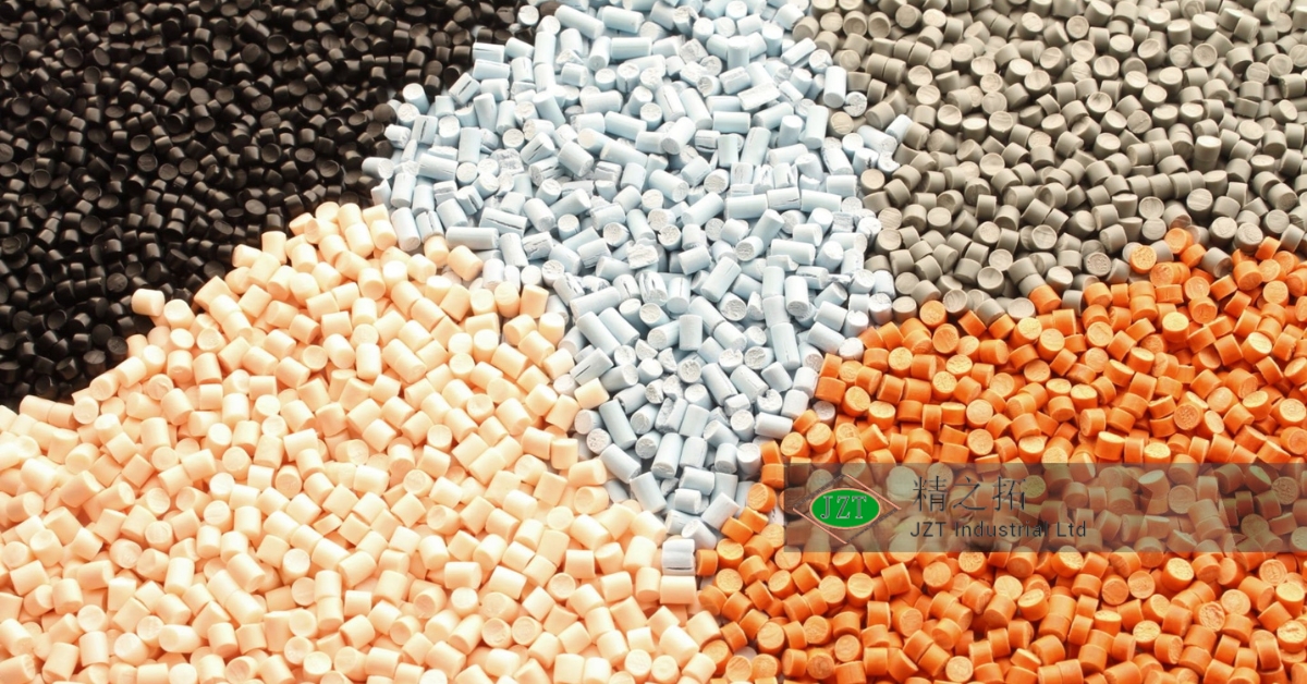
Plastic injection molding is primarily used for thermoplastics—materials that can be melted, molded, and solidified multiple times without losing their properties. Common thermoplastics used in injection molding include polypropylene (PP), polyethylene (PE), and acrylonitrile butadiene styrene (ABS), each chosen for specific properties like durability, flexibility, or impact resistance.
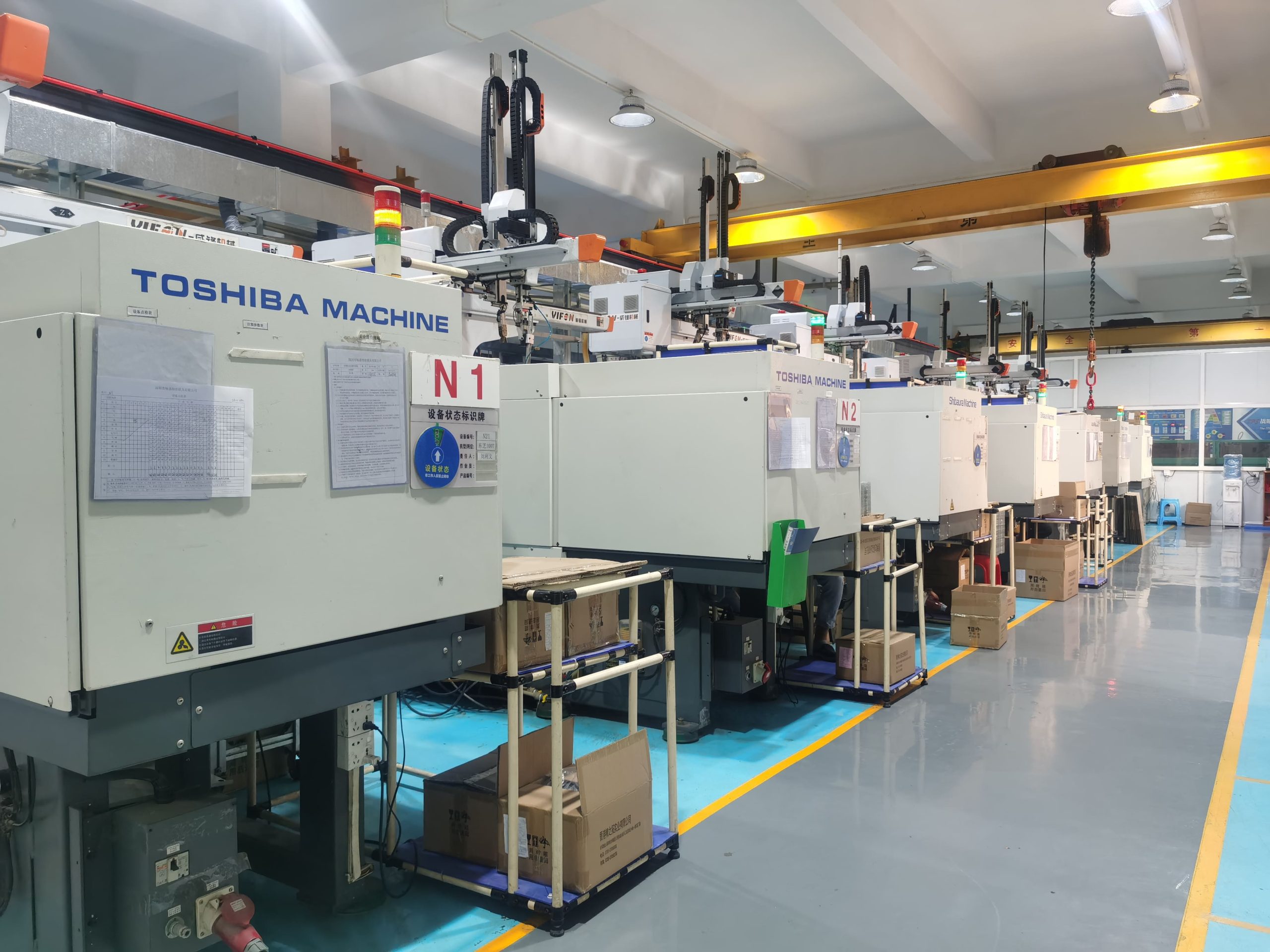
The injection molding machine, also known as a press, is the central piece of equipment used in the process. It consists of three main parts: the injection unit, which melts and injects the plastic; the mold, where the plastic takes shape; and the clamping unit, which holds the mold closed during the injection process. These machines can vary in size and capacity, but their basic function remains the same across different applications.
Understanding how these components work together allows engineers to make better design choices for their plastic parts. For example, selecting the appropriate material for a project involves understanding the material’s behavior under high heat and pressure, as well as how it interacts with the mold during cooling. Additionally, engineers need to design molds that can accommodate the flow of molten plastic without causing defects like warping or incomplete filling.
Key Components of the Injection Molding Process
The success of any injection molding project depends on several critical factors, starting with the choice of materials and ending with the design of the mold. The following are some of the key components that every engineer should consider when designing for plastic injection molding:
The Mold\
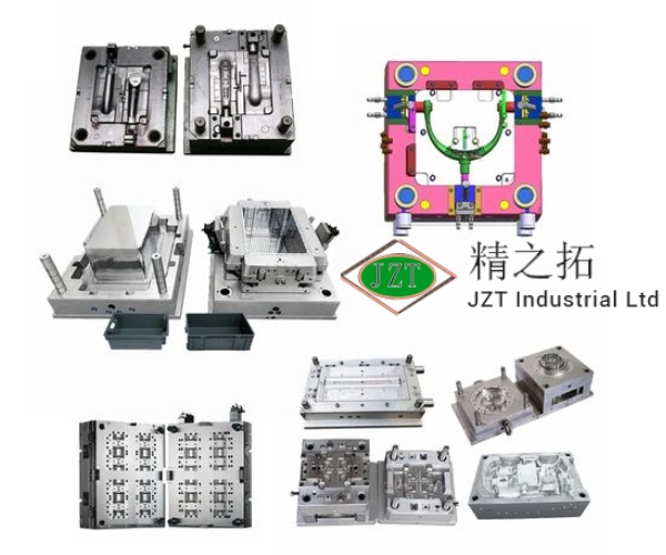
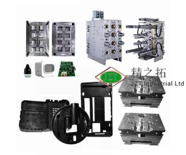
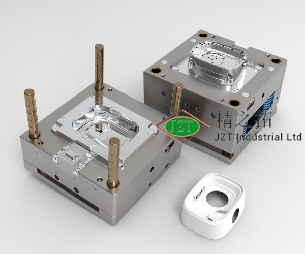
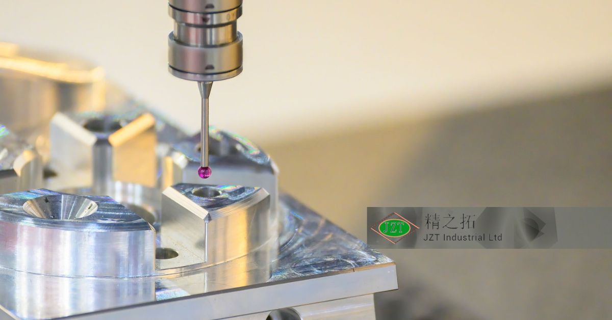
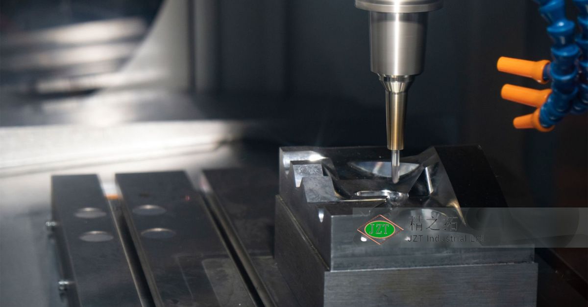
The mold is the heart of the injection molding process. It is a custom-designed tool that determines the shape of the final product. Molds are typically made from steel or aluminum and can be quite expensive to produce. Therefore, getting the mold design right is crucial to minimizing costs and ensuring the production of high-quality parts.
Material Selection\
Choosing the right plastic material is one of the most important decisions in injection molding. The material you select will determine the part’s strength, flexibility, resistance to heat, and overall durability. Different materials are suited for different applications, so it is important to understand the specific requirements of your product before making a selection.
Injection Molding Machines\
These machines vary in size and complexity, depending on the type of product being produced. The choice of machine will affect production speed, precision, and the overall cost of the project. For instance, machines with higher clamping force are needed for larger parts, while smaller parts may require less force but higher precision.
Cooling Systems\
Once the plastic is injected into the mold, it must cool before the part can be ejected. Cooling time is a significant factor in the overall production cycle, so efficient cooling systems are essential to reducing cycle time and improving product quality.
By understanding these key components and how they interact during the injection molding process, engineers can make informed decisions that optimize both the design and manufacturing phases of their projects.
Material Selection in Injection Molding
Types of Plastics: Thermoplastics vs. Thermosetting Plastics
One of the first steps in any plastic injection molding project is selecting the right materials. Plastic materials are generally categorized into two types: thermoplastics and thermosetting plastics. Each category has distinct properties that make them suitable for different applications.
Thermoplastics, such as polypropylene, polyethylene, and polystyrene, are the most commonly used materials in plastic injection molding. They can be melted and remolded multiple times without degrading their properties. This makes thermoplastics ideal for high-volume production and recycling. Thermosetting plastics, on the other hand, undergo a chemical change when heated and can only be molded once. Once they are set, they cannot be re-melted or re-shaped, which makes them suitable for applications that require high heat resistance and durability, such as electrical insulators or heat-resistant components.
Understanding the key differences between these two types of plastics helps engineers make informed decisions about which material is best suited for their specific project. For instance, thermoplastics are generally preferred for parts that need to be flexible or have intricate designs, while thermosetting plastics are better for parts that must withstand high temperatures or harsh environments.
Material Properties to Consider
When selecting a material for injection molding, it is important to consider several key properties that will affect the performance and functionality of the final product:
Durability\
The strength and durability of the plastic are crucial for products that will be subject to wear and tear. Materials like ABS and nylon are known for their toughness and impact resistance, making them suitable for automotive parts and industrial applications.
Heat Resistance\
Certain applications, such as electrical housings or automotive engine components, require materials that can withstand high temperatures without deforming. Polycarbonate and PPS (polyphenylene sulfide) are examples of materials with excellent heat resistance.
Flexibility and Elasticity\
For parts that need to be flexible or capable of bending without breaking, materials like polypropylene or thermoplastic elastomers (TPE) are ideal. These materials offer a balance of strength and flexibility, making them perfect for living hinges or snap-fit parts.
By carefully selecting materials based on these properties, engineers can ensure that the final plastic part meets the functional requirements of the application while also optimizing the manufacturing process. The right material selection will also have a direct impact on the part’s durability, heat resistance, and overall performance, reducing the likelihood of defects or failures during use.
Common Materials Used in Injection Molding
Plastic injection molding offers a wide range of material options, each with its own unique set of properties. Some of the most commonly used materials include:
ABS (Acrylonitrile Butadiene Styrene)\
ABS is a strong, impact-resistant material that is commonly used in automotive components, electronic housings, and consumer products. It is known for its toughness and ability to withstand physical impacts, making it ideal for products that need to be durable.
Polypropylene (PP)\
Polypropylene is a lightweight, flexible material that is resistant to chemicals and moisture. It is often used in packaging, medical devices, and automotive parts. Its flexibility makes it ideal for parts that require hinges or snap-fit mechanisms.
Nylon (Polyamide)\
Nylon is a strong, wear-resistant material that offers excellent chemical resistance. It is commonly used in industrial applications, automotive components, and electrical housings. Nylon’s strength and durability make it suitable for high-stress applications.
Polyethylene (PE)\
Polyethylene is a versatile material that comes in various forms, including high-density polyethylene (HDPE) and low-density polyethylene (LDPE). It is used in everything from packaging to automotive parts due to its chemical resistance and flexibility.
By understanding the properties of these materials and their applications, engineers can choose the best material for their specific project. Each material offers a unique balance of strength, flexibility, and resistance to environmental factors, making them suitable for a wide range of plastic parts manufacturing processes.
Mold Design Fundamentals
Types of Injection Molds
The design of the mold plays a crucial role in the success of plastic injection molding. There are several types of molds, and each type serves different purposes depending on the complexity of the part, production volume, and manufacturing needs.
Two-Plate Molds\
A two-plate mold is the most common type used in plastic injection molding. It consists of two halves: one stationary half that contains the sprue (the channel through which the molten plastic enters) and one movable half that opens to release the finished part. These molds are generally simpler to design and less expensive to produce, making them ideal for less complex parts.
Three-Plate Molds\
Three-plate molds introduce an additional plate between the sprue and the mold cavity. This plate separates the runner system (the channels that direct molten plastic from the sprue to the mold cavities) from the finished part, which allows for better control of gate placement and reduces visible marks on the finished part. While more expensive and complex, three-plate molds are often used for parts that require multiple gates or more precise control of the molding process.
Family Molds and Single-Cavity Molds\
Family molds are used to produce different parts in a single cycle by placing multiple cavities within the same mold, each designed for a different part. This is an efficient way to produce multiple components of an assembly at the same time, reducing overall production costs. However, balancing the flow of molten plastic across different part geometries can be a challenge.
Single-cavity molds, on the other hand, produce only one part per cycle. These molds are simpler to design and maintain but can result in longer production times if large quantities of parts are needed. Single-cavity molds are often used for large parts or projects that require high precision.
Key Mold Design Considerations
Designing an injection mold requires attention to a variety of factors that influence the overall efficiency, cost, and quality of the final product. Engineers must balance the technical requirements of the part with the practical limitations of the mold-making process.
Mold Material: Steel vs. Aluminum\
Molds are typically made from either steel or aluminum. Steel molds are more durable and can withstand higher production volumes, making them ideal for mass production of plastic parts. However, steel molds are more expensive and time-consuming to produce. Aluminum molds, on the other hand, are cheaper and faster to manufacture but have a shorter lifespan. They are often used for prototype molds or low-volume production runs.
Mold Layout: Sprue, Runners, Gates, and Cooling Channels\
The layout of the mold is critical to ensuring even distribution of the molten plastic and effective cooling. Sprues and runners are the channels that direct the plastic from the injection unit into the mold cavities. Gates are the small openings through which the plastic enters the cavity. The placement and size of gates can affect the quality of the part, especially in terms of visible marks and stress concentrations.
Cooling channels are embedded within the mold to reduce cycle time by quickly cooling the molten plastic. The design of the cooling system directly impacts the production speed and the quality of the finished part. A well-designed cooling system can help prevent defects such as warping and shrinkage by ensuring uniform cooling across the entire part.
Importance of Mold Durability and Maintenance\
Mold durability is a key factor in the long-term success of any injection molding project. High-quality molds made from durable materials can withstand thousands of cycles without significant wear or degradation. However, even the best molds require regular maintenance to ensure optimal performance. Engineers must plan for routine inspections and preventive maintenance to avoid costly production delays caused by mold failure.
By carefully considering these factors during the mold design phase, engineers can create molds that not only meet the technical requirements of the part but also optimize production efficiency and reduce long-term costs.
Part Design for Injection Molding
Wall Thickness Considerations
Wall thickness is one of the most important aspects of plastic part design. Consistent wall thickness helps ensure uniform material flow during the injection molding process, which reduces the risk of defects such as warping, sink marks, or incomplete fills. Thick walls can lead to longer cooling times and increase the likelihood of shrinkage, while thin walls may cause flow issues, resulting in incomplete filling or weak parts.
In general, the wall thickness should be kept as consistent as possible throughout the part. If thickness variations are necessary, the transition between thick and thin areas should be gradual to avoid creating stress points. Designing parts with uniform wall thickness also helps reduce production costs by speeding up the cycle time and improving material efficiency.
Draft Angles
Draft angles are a critical design consideration in injection molding because they allow the part to be easily ejected from the mold without causing damage. A draft angle is a slight taper applied to the vertical surfaces of a part, which helps prevent sticking and reduces the force required to eject the part.
Without adequate draft, the part may get stuck in the mold, leading to defects or even damage to the mold. The recommended draft angle depends on the material used and the part’s design, but a general rule of thumb is to use a draft angle of 1 to 2 degrees for most materials. For parts with textured surfaces, a larger draft angle may be required to accommodate the texture.
By incorporating draft angles into the design, engineers can reduce wear on the mold and improve production efficiency by minimizing the risk of part sticking or damage during ejection.
Ribs and Bosses for Structural Integrity
Ribs and bosses are commonly used in plastic part design to increase structural integrity without adding significant weight or material cost. Ribs are thin, vertical walls that reinforce larger, flat sections of a part, helping to prevent warping or bending under load. Bosses are raised sections designed to accommodate screws, fasteners, or other components, providing a secure attachment point within the part.
When designing ribs, it is important to maintain a balance between strength and moldability. Ribs should be designed with a thickness that is proportional to the wall thickness of the part—typically around 60% of the wall thickness. Ribs that are too thick can cause sink marks on the surface of the part, while ribs that are too thin may not provide adequate reinforcement.
Bosses should also be carefully designed to prevent defects such as sink marks or voids. The wall thickness around a boss should be consistent with the rest of the part, and fillets should be added to the base of the boss to reduce stress concentrations.
By incorporating ribs and bosses into the design, engineers can create lightweight, strong parts that meet the functional requirements of the application while minimizing material usage.
Undercuts and Side Actions
Undercuts are features that prevent the part from being ejected from the mold in a straight line. They can include holes, grooves, or protrusions that require additional mechanisms, such as side actions or lifters, to mold and release the part. While undercuts can add complexity and cost to the mold design, they are sometimes necessary for achieving certain part geometries.
Side actions are mechanical components in the mold that move laterally to create and release undercuts. Designing undercuts with removable side actions allows engineers to create complex geometries without sacrificing the ability to eject the part cleanly. However, the use of side actions increases the complexity and cost of the mold, so engineers should evaluate whether simpler design solutions are available before incorporating undercuts.
To avoid undercuts altogether, engineers can consider alternative design solutions, such as redesigning the part geometry to eliminate the need for side actions or breaking the part into multiple pieces that can be assembled after molding.
Gate Design and Placement
Types of Gates
Gates are the small openings through which molten plastic enters the mold cavity. The design and placement of gates have a significant impact on the quality and appearance of the final part. Different types of gates are used depending on the part’s size, geometry, and aesthetic requirements.
Edge Gates\
Edge gates are the most commonly used gate type. They are located along the parting line of the mold and feed the molten plastic into the side of the part. Edge gates are simple to design and can accommodate a wide range of part geometries. However, they can leave visible marks on the part surface, which may be undesirable for cosmetic parts.
Center Gates\
Center gates are typically used for round or symmetrical parts. The gate is located in the center of the part, allowing the plastic to flow evenly in all directions. This helps reduce warping and ensures uniform filling, but the gate mark will be visible on the surface of the part.
Submarine Gates\
Submarine gates are used to minimize visible marks on the part surface. The gate is located below the parting line, and the plastic enters the mold through a small tunnel. Submarine gates are often used for parts where appearance is important, but they require more complex mold designs.
Best Practices for Gate Placement
Proper gate placement is critical for achieving high-quality parts. The location of the gate affects how the plastic flows into the mold cavity, which in turn impacts the part’s appearance, strength, and dimensional accuracy.
Gates should be placed in a way that ensures even filling of the mold cavity. Uneven filling can lead to defects such as warping, voids, or incomplete filling. Gates should also be located in areas where the plastic will cool evenly to prevent shrinkage or sink marks.
When designing gates, it is important to consider both the aesthetic and functional requirements of the part. For example, gates should be placed in non-visible areas whenever possible to avoid leaving visible marks on the finished part. Additionally, the gate size should be optimized to ensure proper flow without causing excessive stress on the part.
By carefully considering gate design and placement, engineers can improve the quality of the final part and reduce the risk of defects during the molding process.
Cooling System Design
Importance of Efficient Cooling Systems
Cooling time is one of the most significant factors affecting the overall cycle time in injection molding. The faster the part can cool, the quicker it can be ejected from the mold, which increases production efficiency. However, cooling must be done evenly and efficiently to avoid defects such as warping, sink marks, or internal stresses.
Efficient cooling system design is crucial for reducing cycle times and ensuring the dimensional stability of the part. The cooling system consists of channels embedded within the mold, through which a cooling fluid, usually water, circulates to absorb the heat from the molten plastic. The design and placement of these cooling channels play a critical role in achieving uniform cooling.
Cooling System Types
There are several types of cooling systems used in injection molding, each designed to optimize heat transfer and reduce cycle time.
Spiral Cooling\
Spiral cooling channels are often used for cylindrical or round parts. The spiral design ensures that the cooling fluid flows evenly around the entire part, providing consistent cooling and reducing the risk of warping.
Baffles and Bubblers\
Baffles and bubblers are used in areas of the mold where space is limited, and conventional cooling channels cannot be used. Baffles are thin plates inserted into the cooling channels to direct the flow of cooling fluid, while bubblers are tubes that deliver cooling fluid directly to the core of the mold. These techniques help improve cooling in areas that are difficult to reach with standard channels.
Conformal Cooling\
Conformal cooling is an advanced cooling technique that uses 3D-printed molds with cooling channels that follow the contours of the part. This allows for more precise and efficient cooling compared to traditional straight channels. Conformal cooling is particularly beneficial for complex geometries where traditional cooling methods may be insufficient.
By using the right cooling system design, engineers can significantly reduce cycle time, improve part quality, and reduce the risk of defects caused by uneven cooling.
Optimizing Cooling Time
In addition to choosing the right cooling system, engineers can optimize cooling time by considering factors such as the material’s thermal properties, part geometry, and mold design. For example, materials with high thermal conductivity, such as aluminum, cool faster than materials with lower conductivity, such as steel.
Engineers should also design parts with consistent wall thickness to promote even cooling. Variations in wall thickness can cause certain areas to cool faster than others, leading to warping or sink marks.
Finally, advanced cooling techniques such as conformal cooling or the use of thermally conductive materials can further optimize cooling time and improve overall production efficiency.
Mold Flow Analysis: Optimizing the Design
What is Mold Flow Analysis?
Mold flow analysis is a critical tool in the design process of plastic injection molding. It is a simulation-based technology that allows engineers to visualize and optimize how molten plastic flows within the mold cavity during the injection process. By using mold flow software, engineers can predict potential issues such as incomplete filling, air traps, weld lines, and excessive warping before physical molds are created.
This simulation helps identify and solve design problems in advance, saving both time and money during the production phase. With mold flow analysis, engineers can make adjustments to the part geometry, gate locations, material selection, and cooling channels to ensure that the final product will be free of defects and manufactured efficiently. It also allows designers to simulate various material behaviors, filling patterns, and cooling cycles, providing insights that lead to more accurate and robust mold designs.
Mold flow analysis is particularly important when dealing with complex part geometries, large parts, or materials that are prone to warping. By optimizing the mold and process parameters, engineers can improve the manufacturability and overall quality of the custom plastic parts, reducing the likelihood of defects that can affect performance.
Benefits of Simulation
There are numerous advantages to using mold flow analysis in injection molding. The primary benefit is that it allows for the early detection of design issues that would otherwise be difficult to identify until the physical mold is built and tested. This reduces costly modifications and minimizes the need for trial-and-error adjustments during production.
- Optimizing Material Flow\
Mold flow analysis can help engineers determine the best way to fill the mold cavity, ensuring that the molten plastic reaches every area of the part uniformly. This is particularly important for preventing defects such as air traps, short shots, and uneven cooling, which can result in poor part quality or functional issues. - Improving Cooling Efficiency\
By simulating the cooling process, engineers can identify areas where the part might cool too quickly or too slowly, leading to potential warping or shrinkage. With mold flow analysis, cooling channels can be optimized to promote even cooling and reduce cycle time, leading to higher-quality parts and faster production. - Reducing Warping and Shrinkage\
Warping and shrinkage are common problems in injection molding, especially for parts with uneven wall thickness or complex geometries. Mold flow analysis can predict where these issues are likely to occur and suggest design changes to mitigate them, such as adjusting wall thickness, gate placement, or cooling channel design. - Predicting and Preventing Weld Lines\
Weld lines, which occur when two flow fronts of molten plastic meet and solidify, can weaken the part and affect its aesthetic quality. Mold flow analysis allows engineers to see where weld lines are likely to form and make adjustments to reduce their impact, such as altering gate locations or using materials with better flow characteristics.
In summary, mold flow analysis is an invaluable tool that allows engineers to optimize the design and manufacturing process, improving part quality, reducing defects, and speeding up production times. It also gives manufacturers the confidence to proceed with production, knowing that the mold design has been thoroughly tested and validated.
Surface Finish and Texture
Common Surface Finishes
The surface finish of a plastic part plays an important role not only in its appearance but also in its functionality. Injection molding allows for a wide range of surface finishes, from smooth and polished to matte or textured, depending on the mold’s surface and the desired properties of the final product.
Polished Finish\
A polished surface provides a high-gloss finish that is often used for cosmetic parts where appearance is critical. It is achieved by polishing the mold cavity to a mirror-like finish, resulting in parts with a shiny, smooth surface. This finish is commonly used in consumer goods, automotive interiors, and electronics housings where aesthetics are important.
Matte Finish\
A matte finish provides a non-reflective surface, which is ideal for parts that need to minimize glare or fingerprints. This type of finish is achieved by lightly texturing the mold surface, creating a uniform matte appearance on the final part. Matte finishes are often used in automotive parts, medical devices, and industrial components where functionality is prioritized over appearance.
Textured Finish\
Textured finishes are created by adding patterns to the mold surface. These patterns can range from fine grains to deep, embossed textures, depending on the application. Textures can serve both decorative and functional purposes, such as improving grip, hiding imperfections, or reducing glare. Textured surfaces are commonly used for products like tool handles, automotive dashboards, and packaging materials.
The choice of surface finish depends on both the aesthetic requirements and the functional needs of the product. For example, a polished finish may be desirable for consumer electronics, while a textured surface might be more suitable for industrial equipment that requires a non-slip grip.
How Surface Finish Impacts Product Functionality
The surface finish of a part can significantly affect its performance in different applications. For example, a high-gloss finish may look attractive, but it can also highlight imperfections such as flow lines or sink marks, which may be less visible on a matte or textured surface.
Surface texture can also improve the functionality of a product. For example, a textured surface can improve the grip of a tool handle or reduce the likelihood of fingerprints on a touchscreen device. In some cases, texture can even improve the structural integrity of a part by providing additional reinforcement or improving its resistance to wear and tear.
Additionally, surface finish can influence the part’s ease of cleaning, durability, and overall user experience. A rough or highly textured surface may be more difficult to clean, while a smooth, polished surface may scratch more easily. By considering both the aesthetic and functional requirements of the part, engineers can choose the most appropriate surface finish to meet the product’s needs.
Considerations for Mold Texturing
Texturing a mold requires careful planning and execution, as the texture will be replicated on every part produced. Mold texturing involves etching or engraving patterns into the mold surface, and the depth and complexity of the texture will affect both the appearance and functionality of the final part.
When designing for mold texturing, engineers must consider several factors, including the material being used, the draft angle, and the texture depth. Some materials may not replicate textures as well as others, and deeper textures may require larger draft angles to ensure easy part ejection.
Texturing can also affect the durability of the mold, as more complex textures may wear down faster than smoother surfaces. To extend the lifespan of a textured mold, engineers can use harder materials or apply surface coatings to reduce wear and tear.
By carefully selecting the texture and understanding its impact on both the part and the mold, engineers can ensure that the final product meets both aesthetic and functional requirements while maintaining production efficiency.
Tolerances and Fits in Injection Molding
Importance of Tolerances in Part Design
In plastic injection molding, tolerances refer to the allowable variation in a part’s dimensions. Achieving the correct tolerances is essential for ensuring that parts fit together correctly and function as intended. Tolerances also affect the overall quality and performance of the part, especially in applications where precision is critical, such as automotive or medical components.
Tight tolerances ensure that parts will fit together precisely, reducing the need for post-processing or adjustments during assembly. However, achieving tight tolerances in plastic injection molding can be challenging due to factors such as material shrinkage, mold wear, and machine variability.
Best Practices for Tolerance Allocation
When designing for injection molding, it is important to balance the need for precision with the practical limitations of the manufacturing process. Overly tight tolerances can increase costs and lead to production challenges, while loose tolerances can result in parts that do not fit or function properly.
Shrinkage Allowance\
Plastic materials shrink as they cool, and the amount of shrinkage varies depending on the material and the part geometry. Engineers must account for shrinkage when designing parts and setting tolerances. Mold flow analysis can help predict shrinkage and guide the design of the mold to ensure accurate dimensions.
Draft and Ejection Forces\
Adding draft angles to the design can help ensure smooth ejection from the mold, reducing the likelihood of damage to the part or the mold. Tighter tolerances may require more precise control over draft angles and ejection forces, especially in complex geometries.
Tool Wear\
Over time, molds can wear down, especially when producing high volumes of parts. This wear can affect the accuracy of the mold and lead to parts that fall outside of their specified tolerances. Regular maintenance and inspection of molds are essential to maintaining consistent part quality.
By understanding the factors that influence tolerances and designing accordingly, engineers can ensure that parts meet the required specifications while keeping production costs under control.
Avoiding Common Defects in Injection Molding
Typical Defects in Injection Molding
Injection molding is a highly efficient process, but it is not without its challenges. Various defects can occur during production, affecting the quality and performance of the final product. Some of the most common defects include:
Warping\
Warping occurs when different parts of the plastic part cool at different rates, causing the part to bend or twist. This can result from uneven wall thickness, improper cooling, or inadequate mold design.
Sink Marks\
Sink marks are depressions that form on the surface of a part when thicker sections of the plastic take longer to cool and shrink more than the surrounding material. They are commonly caused by improper cooling, excessive wall thickness, or inadequate packing pressure.
Flash\
Flash is the excess plastic that leaks out of the mold cavity and forms along the parting line. It occurs when the mold does not close tightly enough, or the injection pressure is too high.
Short Shots\
A short shot occurs when the mold cavity is not completely filled with plastic, resulting in an incomplete part. This can be caused by inadequate injection pressure, a blocked gate, or insufficient material flow.
How to Design Against Defects
To avoid these common defects, engineers must carefully consider the design of both the part and the mold. Here are some best practices to minimize the risk of defects:
Uniform Wall Thickness\
Maintaining consistent wall thickness throughout the part helps ensure even cooling and reduces the risk of warping and sink marks. If variations in wall thickness are necessary, gradual transitions should be used to minimize stress.
Optimized Cooling System\
A well-designed cooling system helps prevent defects by ensuring that the part cools evenly. Mold flow analysis can be used to identify areas that are prone to uneven cooling and guide the design of cooling channels.
Proper Gate Placement\
Gates should be placed in a location that promotes even filling of the mold cavity. Improper gate placement can lead to short shots, sink marks, and weld lines. Engineers should use simulation tools to determine the best gate location for each part.
Mold Maintenance Tips
Regular maintenance is essential for preventing defects and ensuring the longevity of the mold. Molds should be inspected regularly for wear and damage, and any issues should be addressed promptly. Proper cleaning and lubrication of the mold components can also help prevent defects and improve part quality.
By following these best practices, engineers can design parts and molds that minimize the risk of defects and ensure high-quality production.
Sustainability in Injection Molding
Sustainable Material Choices
As industries increasingly focus on sustainability, the use of eco-friendly materials in plastic injection molding is becoming more common. Engineers can choose from a variety of sustainable materials, including biodegradable plastics, recycled plastics, and bio-based polymers.
Bio-Based Plastics\
Bio-based plastics are made from renewable resources such as corn starch, sugarcane, or algae. These materials offer a more sustainable alternative to traditional petroleum-based plastics, reducing the environmental impact of production.
Recycled Plastics\
Using recycled plastics in injection molding helps reduce waste and minimize the use of virgin materials. Recycled plastics can be used for both low-grade and high-performance applications, depending on the quality of the recycled material.
Energy-Efficient Manufacturing Practices
Energy consumption is a major consideration in injection molding, especially for large-scale production. Engineers can implement energy-efficient practices to reduce the carbon footprint of the manufacturing process.
Reducing Cycle Time\
One of the most effective ways to reduce energy consumption is to shorten the production cycle time. Optimizing the cooling system, reducing wall thickness, and using faster-curing materials can help achieve this goal.
Electric Injection Molding Machines\
Electric injection molding machines are more energy-efficient than traditional hydraulic machines. They consume less energy and produce less waste heat, making them a more sustainable option for manufacturers.
Waste Reduction Strategies
Waste reduction is another key aspect of sustainable manufacturing. By optimizing material usage and reducing scrap, engineers can minimize waste and lower production costs.
Material Recycling\
Recycling plastic waste generated during the molding process is a common practice in the industry. Sprues, runners, and other excess material can often be ground up and reused, reducing the need for virgin materials.
Design for Manufacturability\
Designing parts with sustainability in mind can also help reduce waste. For example, engineers can design parts that require less material or can be assembled without fasteners, reducing both material usage and production complexity.
Cost Considerations in Injection Mold Design
Cost Drivers in Injection Molding
The cost of plastic injection molding is influenced by several factors, including the complexity of the mold, the materials used, and the production volume. Understanding these cost drivers can help engineers make informed decisions to optimize their designs and minimize production costs.
Mold Complexity\
Complex molds with multiple cavities, intricate geometries, or special features such as side actions or inserts are more expensive to produce. Simplifying the mold design can help reduce upfront costs, but it is important to balance simplicity with the functional requirements of the part.
Material Costs\
The cost of raw materials varies depending on the type of plastic used. High-performance materials such as polycarbonate or PEEK are more expensive than standard materials like polypropylene or ABS. Engineers should consider the cost-performance trade-offs when selecting materials for a project.
Cycle Time\
Shortening the cycle time can reduce production costs by increasing the number of parts produced per hour. Optimizing the mold design and using efficient cooling systems can help achieve faster cycle times.
Strategies to Reduce Costs
There are several strategies that engineers can use to reduce the overall cost of injection molding without sacrificing quality.
Design Simplification\
Simplifying the part design can reduce the complexity of the mold and shorten the production cycle. Engineers should avoid unnecessary features and focus on designing parts that are easy to mold and assemble.
Optimizing Material Usage\
By selecting materials that are both cost-effective and suitable for the application, engineers can reduce material costs while maintaining part performance. Using recycled materials or bio-based plastics can also help lower costs.
Investing in High-Quality Molds\
While high-quality molds may have a higher upfront cost, they can offer long-term savings by reducing maintenance costs and improving production efficiency. Durable molds made from high-grade materials can withstand thousands of cycles without significant wear, making them a good investment for high-volume production.
Advances in Injection Molding Technology
Automation in Injection Molding
Automation has become increasingly important in modern injection molding, helping to improve efficiency, reduce labor costs, and enhance product quality. Automated systems can handle tasks such as material handling, mold loading, and part inspection, allowing for faster and more accurate production.
Robotics\
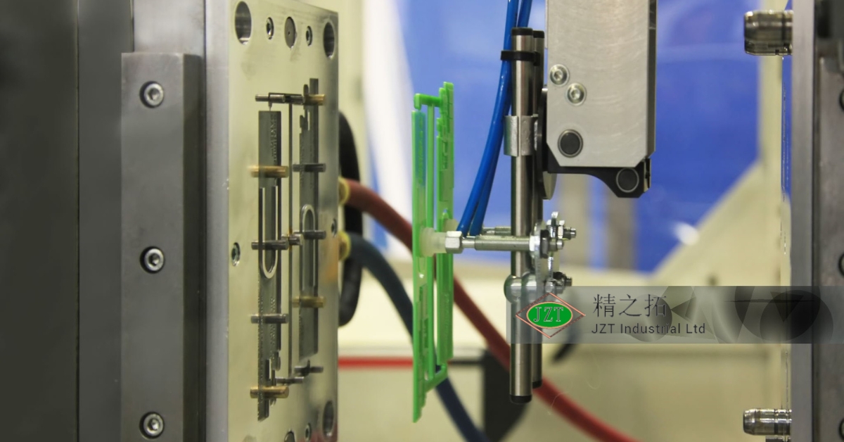
Robots are commonly used in injection molding to handle repetitive tasks such as removing parts from the mold, trimming excess material, or assembling components. By automating these tasks, manufacturers can reduce labor costs and improve production speed.
Quality Control Systems\
Automated quality control systems use sensors and cameras to inspect parts during production, ensuring that they meet the required specifications. These systems can detect defects in real time, allowing for immediate corrective actions to be taken.
3D Printing in Mold Design
3D printing has revolutionized the way molds are designed and prototyped. With additive manufacturing, engineers can create complex mold designs that would be difficult or impossible to achieve with traditional machining methods.
Rapid Prototyping\
3D printing allows engineers to create prototypes of molds quickly and cost-effectively. This enables faster design iterations and reduces the time required to bring a product to market.
Conformal Cooling\
3D-printed molds can incorporate conformal cooling channels that follow the contours of the part, providing more efficient and uniform cooling. This advanced cooling method can reduce cycle time and improve part quality.
Smart Injection Molding Machines
Smart injection molding machines use advanced sensors, data analytics, and artificial intelligence to optimize the molding process in real time. These machines can monitor variables such as pressure, temperature, and material flow, allowing for greater control over the production process.
Real-Time Monitoring\
Smart machines can detect issues such as material inconsistencies or machine malfunctions in real time, allowing for immediate adjustments to be made. This reduces downtime and improves production efficiency.
Predictive Maintenance\
By analyzing data from sensors, smart machines can predict when maintenance is needed, helping to prevent unexpected breakdowns and extend the lifespan of the equipment.
Key Takeaways for Engineers
Understanding the key design considerations for plastic injection molding is essential for engineers who want to optimize their projects for both performance and cost. From material selection to mold design, every decision impacts the final product’s quality, functionality, and manufacturability.
By following best practices such as maintaining uniform wall thickness, incorporating draft angles, and optimizing gate placement, engineers can reduce the risk of defects and improve the efficiency of the injection molding process. Mold flow analysis and advanced cooling techniques can further enhance product quality, while automation and smart machines offer new opportunities for improving efficiency and reducing costs.
In an increasingly competitive market, staying up-to-date with the latest advances in injection molding technology is essential for engineers who want to deliver high-quality products on time and within budget.
Conclusion
Plastic injection molding is a versatile and efficient manufacturing process, but it requires careful planning and design to achieve the best results. By understanding the key design considerations, engineers can create custom plastic parts that meet the highest standards of quality and performance while minimizing production costs.
From material selection to mold design and cooling systems, each decision plays a critical role in the success of the project. Advances in technology, such as mold flow analysis, 3D printing, and smart machines, offer new ways to optimize the injection molding process and improve part quality.
By applying the insights from this guide, engineers can ensure that their injection molding projects are successful, efficient, and cost-effective.

