
Plastic Injection Molds: How They Shape Manufacturing
Plastic injection molds shape modern manufacturing by turning molten polymer into repeatable parts at production scale. A mold may produce acceptable trial samples yet struggle after production ramps up: dimensions drift, flash appears, cooling varies, and repeated tool changes push a launch off schedule. The practical answer is to treat plastic injection molds as production systems, with part design, tool construction, process settings, inspection, and maintenance reviewed together.
If you are developing a plastic component for mass production, early tooling decisions will affect part quality, cycle stability, and long-term supply. A supplier that can follow the job from mold design through molding reduces gaps between the team that built the tool and the team expected to run it.
What Are Plastic Injection Molds and What Do They Do?
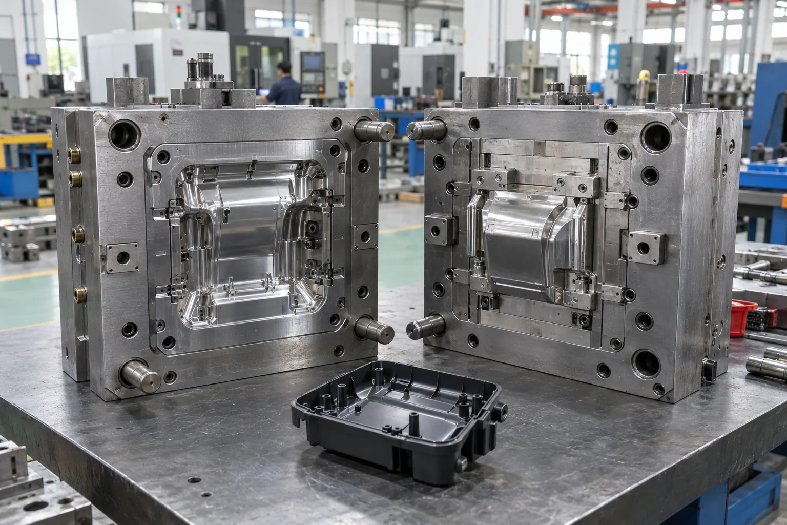
Plastic injection molds are precision tools that define a plastic part's shape, surface, and repeatability while the polymer cools. The cavity forms the outside surface, the core forms internal features, and other systems feed, cool, vent, and release the part. A production-ready mold must repeat that result across planned output, not only during a short trial.
What Should a Buyer Review Before Approving the Tool?
The production test begins here. Review how the tool will run, how the molded part will be measured, and how changes will be controlled after steel is cut.
- Confirm the approved resin, color, shrinkage basis, and annual volume.
- Mark critical dimensions, cosmetic zones, assembly fits, and functional surfaces.
- Define the target press, planned cavity count, and expected automation.
- Agree on trial conditions, sample quantity, inspection records, and issue closure.
| Review area | Question to resolve | Production effect |
|---|---|---|
| Part definition | Are CAD, drawings, revisions, and tolerances aligned? | Prevents conflicting acceptance criteria |
| Tool concept | Do gate, cooling, venting, and ejection fit the part? | Reduces avoidable molding defects |
| Validation | Will samples and process conditions be recorded? | Supports repeatable approval |
| Ownership | Who closes tool and molding issues? | Limits gaps between suppliers |
Key Takeaway: This review connects the drawing, mold, machine, and acceptance plan before production pressure rises. Approve the mold against repeatable production needs, not the appearance of one good sample.
How Do Plastic Injection Molds Run a Production Cycle?
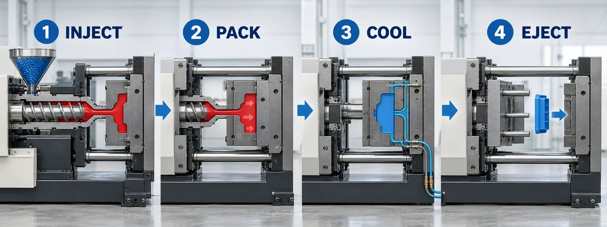
Plastic injection molds run a production cycle by closing, filling, packing, cooling, opening, and ejecting in a controlled sequence. The press melts and meters resin, then pushes it through the runner and gate into the cavity. Packing compensates for shrinkage, cooling sets the part, and ejection releases it for the next cycle.
Which Cycle Conditions Affect Part Consistency?
The cycle only works as a system. A useful injection molding review checks the interaction between the tool, resin, machine, and part rather than adjusting one setting in isolation.
- Melt and mold temperatures affect flow, shrinkage, and surface finish.
- Injection speed and pressure affect filling, weld lines, flash, and burns.
- Packing pressure and time affect sink, weight, and dimensional stability.
- Cooling time and water balance affect cycle time and warpage.
| Cycle stage | Main control | Typical risk when unstable |
|---|---|---|
| Fill | Speed, pressure, temperature | Short shots, burns, weld lines |
| Pack | Pressure, transfer point, time | Sink, voids, weight variation |
| Cool | Water flow, mold temperature, time | Warpage, dimensional drift |
| Eject | Release timing, force, stroke | Drag, stress marks, deformation |
Key Takeaway: The table shows why stable output depends on a controlled window across the full cycle. Record trial settings and part results together so production teams can reproduce an approved condition.
Which Components Control Plastic Injection Mold Performance?
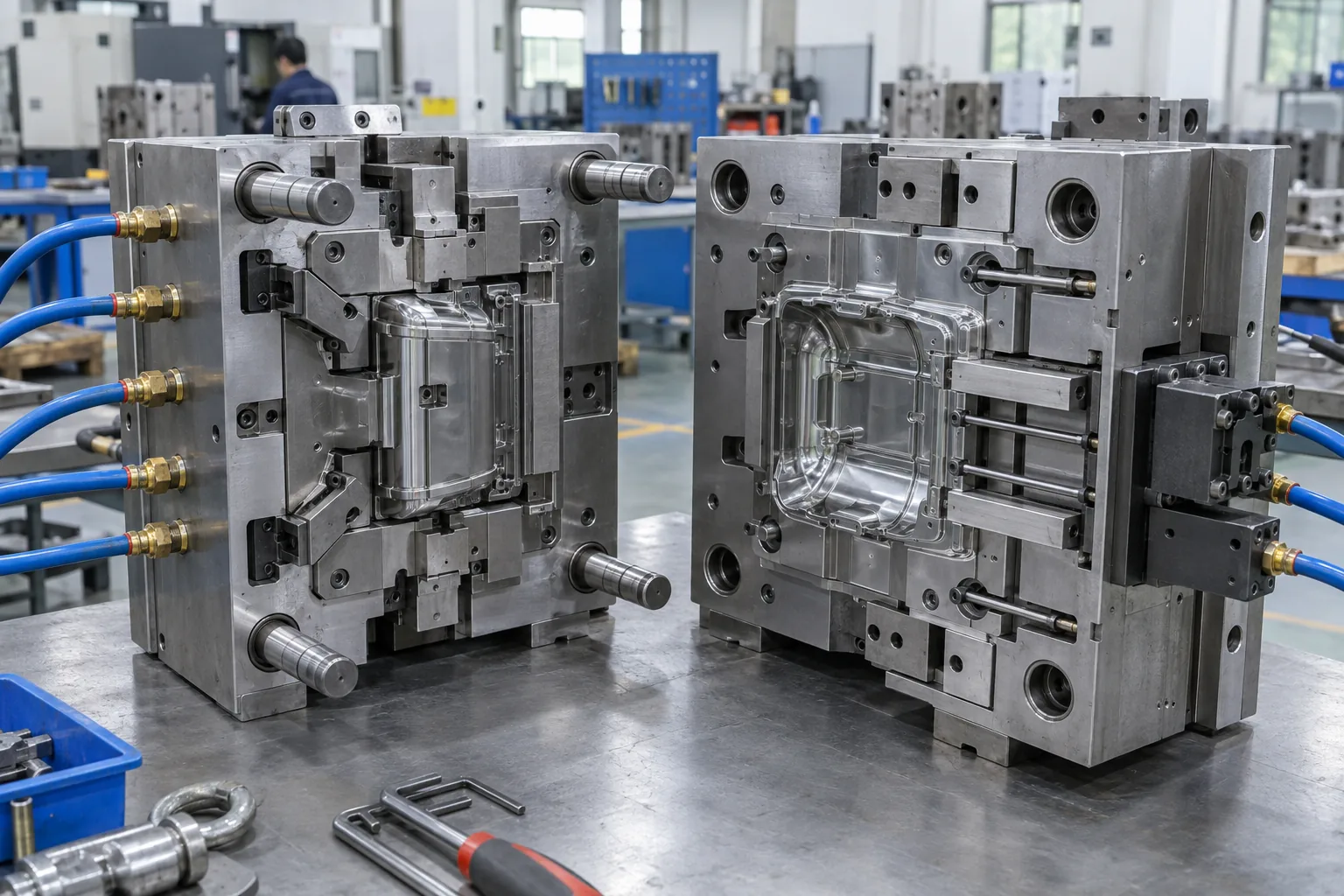
The components inside plastic injection molds control material flow, heat removal, alignment, movement, and part release. Core and cavity geometry create the part, while the mold base, guide system, runner, gate, vents, cooling circuit, and ejectors make repeated cycles possible. Slides, lifters, inserts, and hot-runner hardware add function but also add interfaces that need inspection and maintenance.
How Do Components Turn Into Production Risks?
Interfaces deserve the closest look. For projects that need precision mold and molding support, the review should connect each mechanism to a measurable part requirement.
- Check shutoffs and parting surfaces for flash risk and wear access.
- Check slides and lifters for travel, locking, lubrication, and replacement access.
- Check gates and runners for balanced filling and acceptable vestige.
- Check ejectors for even release without marking critical surfaces.
| Component group | Primary job | Buyer check |
|---|---|---|
| Core and cavity | Form part geometry and finish | Steel condition and dimensional report |
| Feed system | Deliver melt to each cavity | Fill balance and gate location |
| Thermal system | Remove heat consistently | Circuit layout, flow, and connections |
| Motion system | Release undercuts and eject parts | Travel, wear points, and service access |
Key Takeaway: Component reviews work best when each feature traces back to fit, appearance, function, or cycle time. Ask how every moving, sealing, feeding, and cooling feature will be verified and serviced.
How Are Plastic Injection Molds Manufactured?
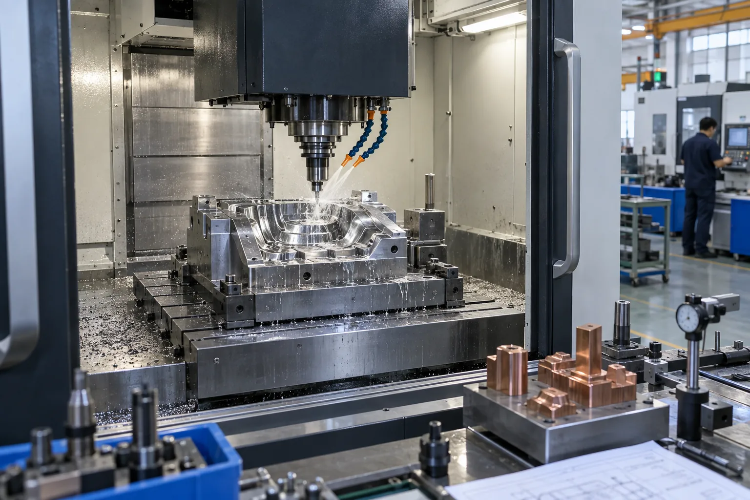
Plastic injection molds are manufactured through design release, steel preparation, precision machining, finishing, assembly, trial, and correction. CNC removes bulk material and creates controlled surfaces, while EDM and wire cutting produce details that milling cannot reach efficiently. Grinding, fitting, polishing, and measurement bring separate components into a working tool.
Where Should Quality Gates Sit During Toolmaking?
Early checks cost less than late corrections. A practical mold manufacturing review places checks after design, rough machining, detail machining, assembly, and trial.
- Freeze the approved part revision and mold specification before machining.
- Inspect electrodes, inserts, shutoffs, and critical steel dimensions between operations.
- Verify cooling circuits, moving actions, sensors, and fittings before the tool enters the press.
- Track trial findings by cause, action, owner, and verification result.
| Toolmaking stage | Main output | Gate before release |
|---|---|---|
| Design | Mold layout and component detail | Engineering review and revision approval |
| Machining | Finished plates, inserts, and electrodes | Dimensional and surface checks |
| Assembly | Fitted mold with working mechanisms | Motion and utility checks |
| Trial | Molded samples and process record | Part inspection and issue list |
Key Takeaway: These gates catch expensive problems while the related work is still accessible. Treat toolmaking as a measured sequence with release criteria, not one long build followed by a single trial.
How Should Part Design Support Reliable Molding?
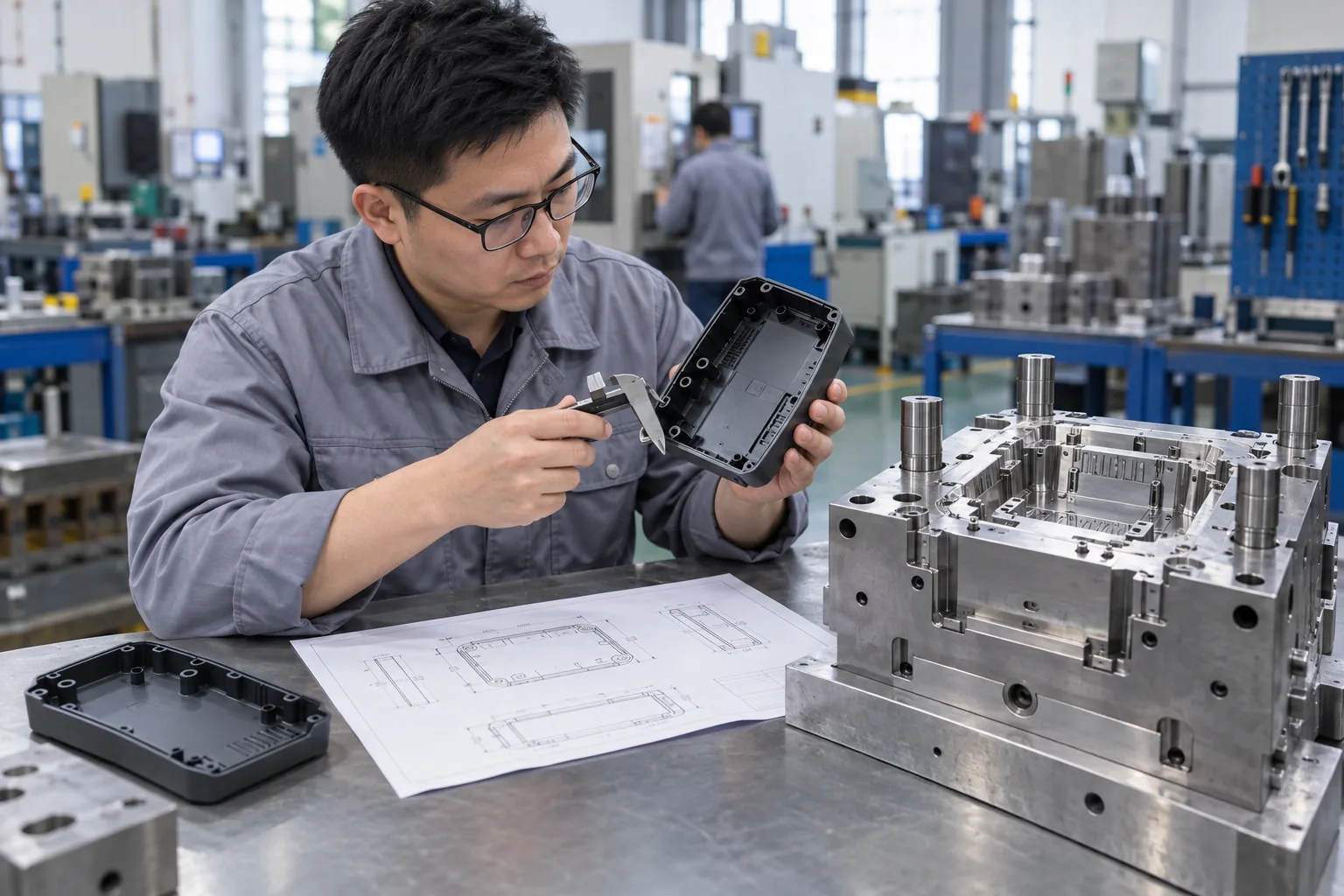
Part design should support plastic injection molds with consistent walls, workable draft, smooth transitions, realistic tolerances, and planned release paths. Thick-to-thin changes can create sink and uneven cooling, while sharp internal corners raise stress and make steel conditions harder to machine. Undercuts may require slides, lifters, collapsible cores, or a part redesign.
What Should a DFM Review Resolve Before Steel Is Cut?
Now bring the review back to the part. A focused engineering review should show what needs a design decision, what needs a tooling feature, and what can be managed in the molding process.
- Review wall transitions, ribs, bosses, radii, and draft together.
- Locate parting lines, gates, ejector marks, and cosmetic boundaries.
- Separate functional tolerances from drawing values that add cost without value.
- Check assembly stack-up, texture allowance, and expected resin shrinkage.
| Design feature | Mold implication | Production question |
|---|---|---|
| Wall thickness | Cooling demand and sink risk | Can sections fill and cool evenly? |
| Draft and texture | Release force and surface drag | Will the part eject without damage? |
| Undercut | Side action or special mechanism | Is added tool complexity justified? |
| Tolerance | Steel adjustment and process control | Is the value tied to function? |
Key Takeaway: This matrix separates cosmetic preferences, functional needs, and avoidable tooling cost. Close DFM decisions before machining so the mold does not become the place where unresolved product design is discovered.
How Do Materials Change Mold and Process Decisions?
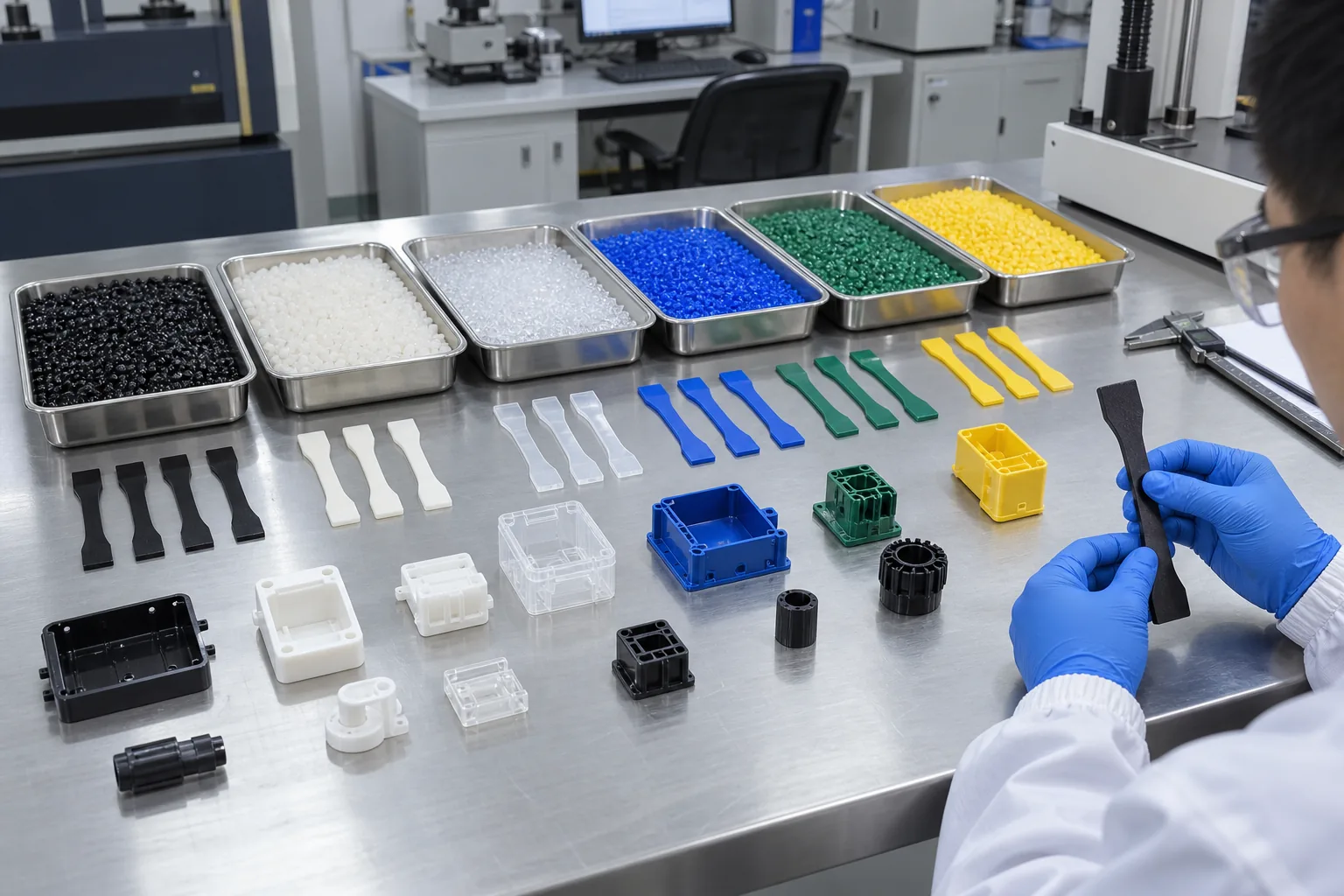
Plastic injection molds must match the selected resin's flow, shrinkage, heat, moisture sensitivity, abrasion, and chemical behavior. A material change can alter gate size, vent demand, cooling time, steel choice, surface treatment, and final dimensions. Filled or flame-rated grades may behave differently from an unfilled base polymer even when their family name looks similar.
Which Material Details Belong in the RFQ?
Material choice reaches every mold system. Give the supplier a named commercial grade when possible, then explain the functional reason behind it so substitutions are reviewed rather than assumed.
- State resin supplier, grade, color, filler, and compliance needs.
- Share operating temperature, chemical exposure, loads, and appearance targets.
- Identify mating materials for 2K molding, overmolding, or assembly.
- Define whether regrind, color masterbatch, or resin alternatives are allowed.
| Material behavior | Mold response | Validation focus |
|---|---|---|
| Higher shrinkage | Steel-safe sizing and controlled packing | Dimensions after conditioning |
| Low flow | Gate and runner review | Fill pattern and pressure demand |
| Abrasive filler | Wear-resistant steel or treatment | Gate, runner, and cavity wear |
| Moisture sensitivity | Drying and handling controls | Surface and mechanical consistency |
Key Takeaway: These links between material behavior and tool design should be settled before the supplier commits to steel conditions. A complete resin specification protects dimensional assumptions and reduces late mold changes.
How Do Cooling, Venting, and Ejection Prevent Defects?
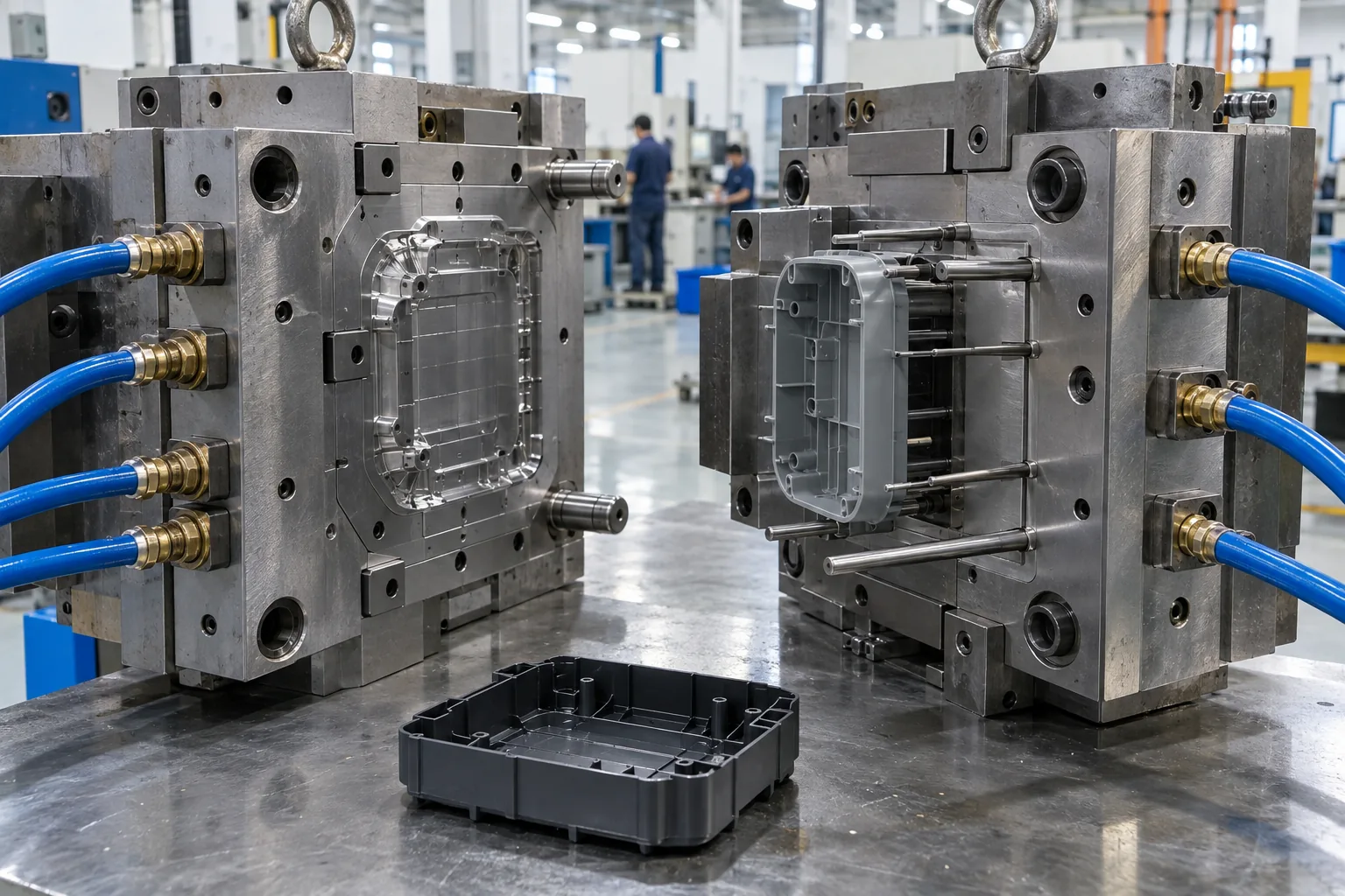
Cooling, venting, and ejection prevent defects by controlling heat, letting displaced air escape, and releasing the part without distortion; all three belong in plastic injection molds from the design stage. Uneven cooling can drive warpage and dimensional drift. Weak venting can contribute to burns or incomplete filling, while poor ejection can leave drag marks, stress, or deformation.
How Can You Trace a Defect Back to the Mold?
Start with the defect pattern. Compare cavity location, defect pattern, process history, and quality inspection data before changing steel or settings.
- Map coolant inlet and outlet temperatures across circuits.
- Check vents for location, cleanliness, depth, and evidence of gas trapping.
- Review ejector contact area, release timing, polish direction, and draft.
- Compare defects by cavity, machine cycle, and production interval.
| Defect | Mold-related cause to check | Evidence to collect |
|---|---|---|
| Warpage | Uneven cooling or shrinkage restraint | Temperature and dimensional map |
| Burn mark | Trapped gas or restricted vent | Defect location and vent condition |
| Short shot | Flow restriction or poor air escape | Fill study and process record |
| Ejector mark | High release force or poor support | Part photos and ejection sequence |
Key Takeaway: The defect pattern often narrows the search faster than random setting changes. Use part evidence and mold-system checks together before ordering a repair.
What Drives the Cost of Plastic Injection Molds?
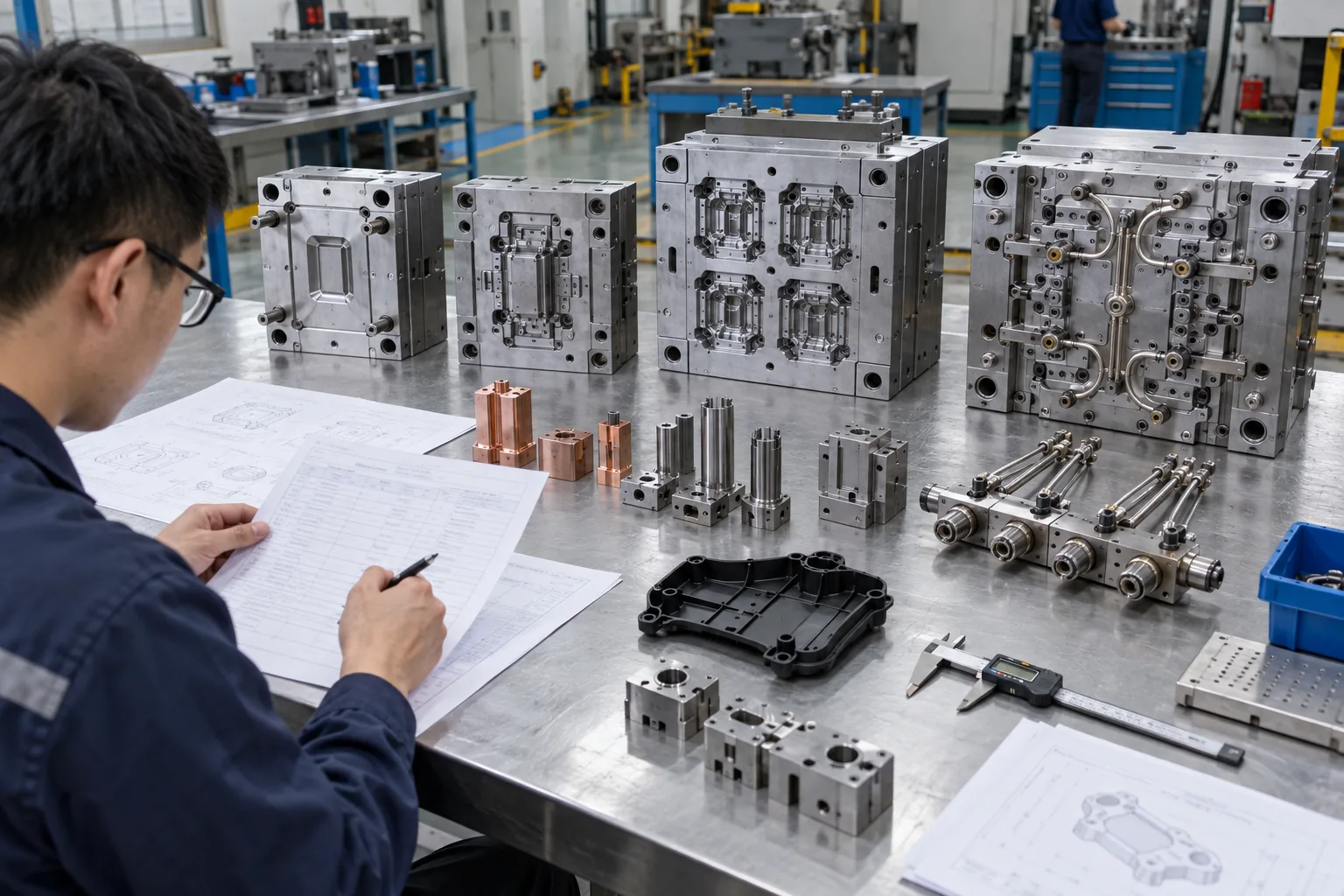
Plastic injection molds cost more when geometry, cavity count, steel, surface finish, side actions, hot runners, inspection, and validation require more engineering or manufacturing work. Tool size and press selection also affect the mold base, handling, and production setup. The lowest tooling quote can create a higher total cost if cycle time, maintenance, scrap, or modification work receives little attention.
How Should You Compare Two Tooling Quotes?
Separate tool price from production cost. Ask each supplier to state the mold specification and manufacturing scope behind the number.
- Compare steel, mold base, cavities, runner type, actions, and spare parts.
- Compare design review, trial quantity, dimensional reports, and sample approvals.
- Check what the quote excludes, including texture, shipping, fixtures, and changes.
- Model expected cycle time, maintenance demand, scrap risk, and annual volume.
| Cost driver | Upfront effect | Long-term effect |
|---|---|---|
| Cavity count | Larger, more complex tool | More output per cycle if balanced |
| Steel and treatment | Higher material and processing cost | Wear and maintenance behavior |
| Side actions | More components and fitting | Added complexity and service demand |
| Cooling and hot runner | More design and hardware | Cycle, material use, and stability |
Key Takeaway: A quote comparison becomes useful only when both suppliers price the same technical scope. Buy against total production requirements, then test every cost-saving proposal for its effect on quality and uptime.
How Should Buyers Validate a Mold for Mass Production?
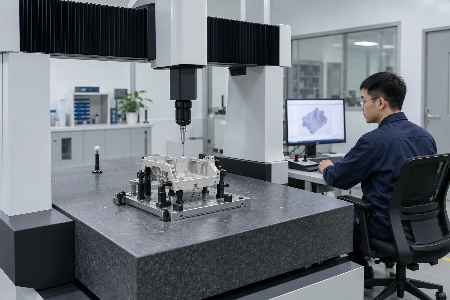
Buyers should validate plastic injection molds with controlled trials, approved material, recorded process conditions, dimensional inspection, cosmetic review, and repeated cycles. A conforming sample shows that the mold can make the part once. Production approval should also show that the process holds part requirements over time and that open issues have owners and closure evidence.
What Evidence Supports a Production Decision?
A good sample is only the starting point. Match the validation package to the part's risks and the supplier's mold and part inspection capability, without requesting paperwork that has no decision value.
- Record machine, resin lot, drying, cycle, temperatures, pressures, and cavity identity.
- Measure critical dimensions across planned cavities and selected time intervals.
- Review appearance, assembly, function, part weight, and defect history.
- Close trial issues with a change record and a verification run.
| Evidence | What it answers | Buyer use |
|---|---|---|
| Trial process sheet | How were approved samples made? | Production setup reference |
| Dimensional report | Do critical features meet the drawing? | Engineering and quality approval |
| Cavity comparison | Does each cavity behave similarly? | Multi-cavity risk review |
| Issue log | Were changes verified after correction? | Launch and supplier follow-up |
Key Takeaway: This package gives procurement, engineering, and quality a shared basis for approval. Release the tool only when part results, process conditions, and open actions tell the same story.
How Can You Move From Tooling to Stable Mass Production?
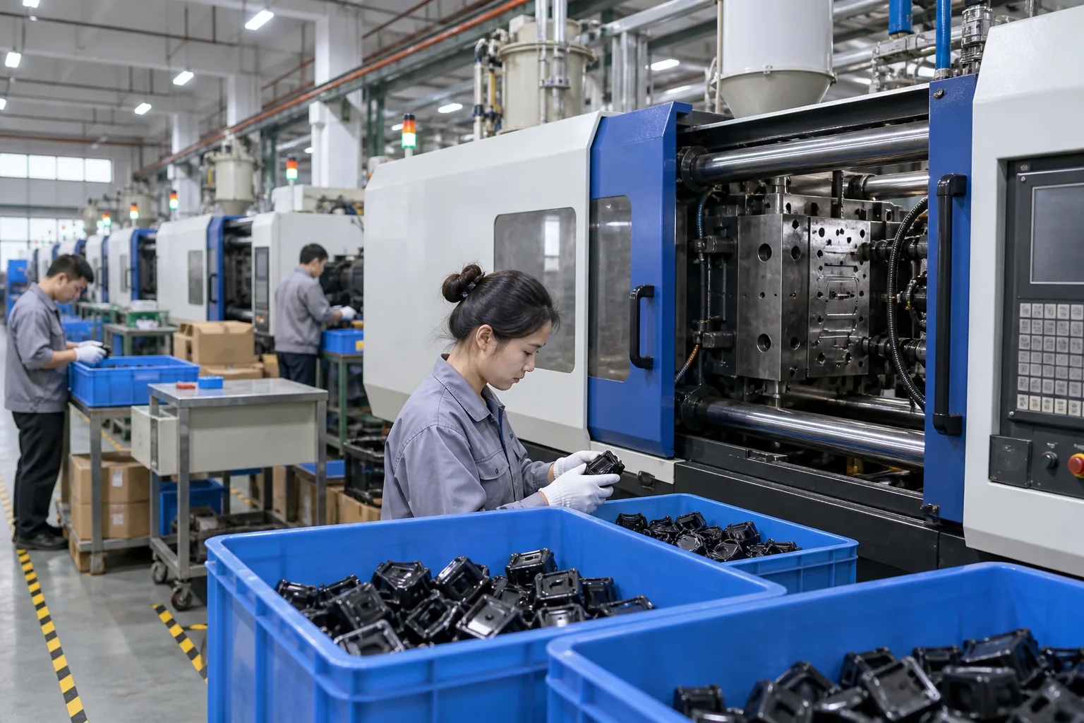
Plastic injection molds move into stable mass production when tool design, trial learning, process settings, inspection methods, and maintenance ownership transfer as one controlled package. Changsheng Mould supports mold development, 30T-380T injection molding, 2K molding, measurement, and assembly within one manufacturing organization. Project-specific capacity, timing, material, tolerance, and validation needs still require technical review before commitment.
What Should You Send for a Tooling Review?
A clear RFQ shortens the review. Send enough detail for engineering and production teams to evaluate the same project, then contact us today to discuss the tool and its path into volume production.
- 3D CAD files and controlled 2D drawings
- Plastic material and approved grade
- Annual volume and ramp plan
- Critical dimensions and cosmetic surfaces
- Assembly, mold, inspection, and project timing requirements
| RFQ input | Why it matters | Decision it supports |
|---|---|---|
| CAD and drawings | Defines geometry, tolerances, and revision control | Mold concept and inspection plan |
| Material and volume | Sets shrinkage, wear, cavity, and cycle needs | Steel, runner, and capacity choices |
| Quality requirements | Identifies critical and cosmetic features | Validation scope and acceptance criteria |
| Launch plan | Aligns trials, approvals, and production timing | Project schedule and resource planning |
Key Takeaway: Together, these inputs let you compare a supplier's technical approach instead of relying on a tooling price alone. Reliable mass production starts with a mold designed around production conditions, not only a mold designed to produce the first sample.
Frequently Asked Questions
- Can I use one injection mold for different plastic materials? Yes, in some cases. The materials must be reviewed for shrinkage, flow, temperature, wear, color change, and dimensional effect before a substitution is approved.
- What's the best mold type for high-volume production? It depends on the part and production requirements. Cavity count, steel, runner system, cooling, actions, target press, annual volume, and maintenance plan should be evaluated together.
- How do I know if my part is ready for injection molding? Usually, several factors should be checked first. Complete CAD, controlled drawings, material, functional tolerances, cosmetic zones, assembly needs, and annual demand give a DFM review enough context.
- Can an existing mold be transferred to another supplier? Yes, after a structured tool review. The receiving supplier should inspect mold condition, interfaces, spare parts, water circuits, prior process data, sample history, and target machine compatibility before production starts.
- How should I judge whether a mold maker can support production? Look beyond the trial sample. Review machining, molding, measurement, issue closure, project communication, maintenance support, and the evidence used to approve repeated production.