CS Molds | Header
CS Molds — Injection Molds (Modules 1–5)
Custom Mold Manufacturing

Custom Injection Mold Manufacturing
for Production-Ready Plastic Parts.

One engineering team takes your part from a first drawing to a validated production tool — DFM review, mold design, precision machining, mold trial, dimensional verification — so the tool you approve is the tool that runs on the machine.
DFM Review Mold Design Precision Machining Mold Trial Validation
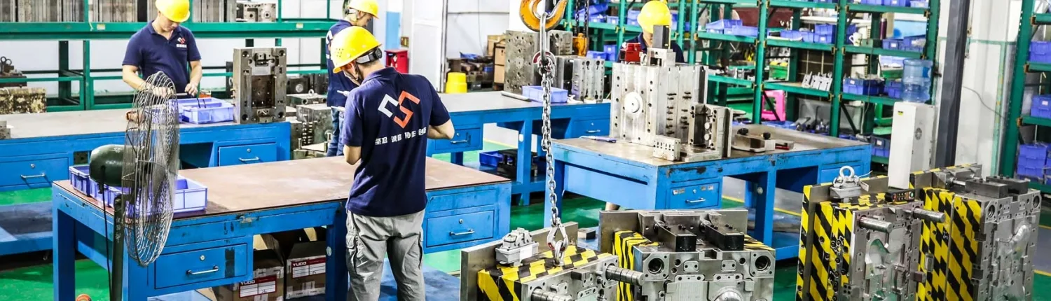
Mold assembly technicians working in the tooling workshop
41
Molding Machines
30–380T
Tonnage Range
IATF
16949 Certified
Production Mold · Shenzhen, CN
30-Second Capability Check

Can We Build Your Mold?

Six answers a sourcing team needs before requesting a formal quote — mold types we build, structures we cut, machining we run in-house, systems we design into every tool, how we prove the mold is ready, and how tooling connects to injection production under one roof.

In-House Tooling + Molding
Mold Types
From a single-cavity prototype tool to production molds that run multi-material and metal-insert parts — the full family of injection tooling comes out of the same tooling floor.
Single-Cavity Multi-Cavity Family 2K Insert Overmold
Complex Structures
Undercuts, threaded features and tight shut-offs stop being a design risk when the tool engineer maps the actions during DFM — before steel is ordered.
Slider Lifter Unscrewing Inserts Complex Shut-off
Precision Machining
33 in-house machining assets keep every critical feature — electrodes, cavities, cooling — under CS Molds' own tolerance record, not a subcontractor's.
CNC HSM EDM WEDM Grinding
Mold Systems
Runner, gate, cooling, venting and ejection are designed together as one production system — the tool leaves fitting with a working process, not a set of holes.
Hot Runner Cold Runner Cooling Venting Ejection
Validation
T0, T1 and dimensional measurement are documented on every tool — so your quality team can approve the mold on evidence, not a promise.
T0 Trial T1 Trial CMM Measurement Improvement
Production Support
41 injection machines from 30T to 380T sit next to the tooling shop — so the mold you approve today can start molding parts tomorrow, without a supplier hand-off.
30T–380T 2K Molding Mass Production Tool Transfer
If your project touches two or three of these capabilities at once, a short engineering review is the fastest way to a real answer. Send your drawings, tolerances and target volume — you'll get a written assessment back, not a template.
Talk to Engineering
Find Your Project Type

What Kind of Mold Project Are You Working On?

Every mold conversation starts differently. Below are the five project shapes we quote most often — pick the one that matches your case, and you'll see what we review up front and what you receive back.

01 · New Build
New Product Mold
Your Situation
Product design is ready, no mold exists yet, launch window is fixed.
What We Review
Part geometry, resin, target cavities, gate strategy, critical tolerances.
What You Receive
DFM report, mold concept, quote and a T0 target date you can plan against.
02 · Precision
Complex / Precision Mold
Your Situation
Tight tolerances, thin walls, deep cavity or an unusual part geometry.
What We Review
Critical dimensions, tool steel selection, insert strategy, cooling design.
What You Receive
Engineering proposal, risk register, sample expectations at T0.
03 · Volume
Multi-Cavity Production Mold
Your Situation
Annual volume needs 2–48 cavities on a stable, long-run tool.
What We Review
Shot weight, target machine size, runner and cooling balance, cycle target.
What You Receive
Cavity layout study, output plan, unit-cost logic behind the cavity count.
04 · Multi-Material
2K / Insert / Overmold Tool
Your Situation
Two-shot, hard-soft, or a part with metal inserts running in one cycle.
What We Review
Material compatibility, shut-off strategy, insert holding, first-shot accuracy.
What You Receive
2K or insert strategy on paper, prototype path, quote with production route.
05 · Transfer
Mold Transfer / Replacement
Your Situation
Existing mold needs a second source, a full replacement, or a duplicate.
What We Review
Current tool status, drawings, molding parameters, IP and ownership terms.
What You Receive
Transfer plan, trial schedule, scope for replacement or duplicate tool.
Your project sits between two of the types above? Send us the case in one paragraph — an engineer will read it and reply with the right project path.
Send Us Your Case
Mold Fundamentals · 01

What Is an Injection Mold?

An injection mold is a precision-machined steel tool that shapes molten plastic into a finished part — under pressure, at a controlled temperature, on a specific machine, cycle after cycle.

The mold is not the machine — it is what the machine holds.

The injection molding machine melts, meters and pushes plastic. The mold decides what that plastic becomes. Melted resin is forced through a sprue and runner into a shaped cavity, held under packing pressure while it cools, then released by ejector pins when the mold opens. Every step is governed by features engineered into the mold long before the first shot.

That is why a good mold is not evaluated by how it looks closed on a bench, but by how the part behaves across thousands of cycles — the shape it holds, the tolerance it keeps, the surface it produces, and the cycle time it allows.

What the Mold Controls in Your Part
Shape & Dimension
Part geometry and every critical tolerance come from the cavity.
Surface Finish
Polish, texture and gate marks are engineered into the tool, not added later.
Repeatability
Cavity balance and cooling decide whether shot #10,000 matches shot #1.
Cycle Time
Cooling design and gate position drive seconds per shot — and unit cost.
Part Cost
Cavity count, material yield and scrap rate all trace back to the mold.
Production Stability
A well-built mold keeps process windows wide and defects out.
Have a part in hand and need to know which of these steps will govern your quality risk? A 20-minute DFM review answers exactly that — free of charge, before any quote.
Start a DFM Review
Mold Fundamentals · 02

Inside a Production Injection Mold.

A production mold is not two blocks of steel — it is ten cooperating systems that together decide whether the part fills, cools, ejects and holds tolerance. Click a point on the diagram to see what each part does and why it matters to your project.

Mold Cross-Section · Schematic
Click any point
FIXED PLATEN PARTING LINE MOVABLE PLATEN A-PLATE · CAVITY SIDE B-PLATE · CORE SIDE 1 2 3 4 5 6 7 8 9 10
Component 01 of 10

Sprue

What it is

The vertical channel that carries molten resin from the machine nozzle into the runner system on the fixed side of the mold.

What it does

Transfers the shot from the barrel into the mold at high pressure and holds a controlled cross-section so the material stays hot and flowable on the way to the gates.

Why it matters

A wrong sprue diameter or angle causes pressure loss, sticking or premature freeze-off — all show up as inconsistent fill on your first shots.

The components above are also the ones that go wrong first when a mold is under-engineered. Send us the 3D file of your part — an engineer will highlight which of these systems will need special attention on your project.
Send Your 3D File
CS Molds | Injection Molds — Modules 6–10
06 / MOLD CYCLE

How an Injection Mold Works

Every plastic part is produced by a repeating seven-stage cycle. Understanding this cycle explains why the mold — not just the machine — controls part quality, cycle time and unit cost across your entire production run.

01
Mold Closing
Two mold halves close under clamp force, sealing the cavity against injection pressure to prevent flash on every shot.
02
Injection
Molten resin is pushed through the sprue, runner and gate into the cavity, driven by the injection unit at a controlled velocity.
03
Filling
Material flows across the cavity, following gate location, wall thickness and venting design to reach every feature completely.
04
Packing & Holding
Additional pressure compensates for shrinkage as the resin cools, locking in the dimensions your drawing calls out.
05
Cooling
Coolant circulates through cavity channels to solidify the part uniformly, controlling warpage and cycle time in one step.
06
Mold Opening
Clamp releases, sliders and lifters retract, and the mold parts separate along the parting line to expose the part.
07
Ejection
Ejector pins, sleeves or strippers push the finished part out cleanly, ready for the next shot without operator intervention.

Five Factors That Drive Cycle Time

DIRECT COST IMPACT
FACTOR 01
Cooling Design
Channel layout and coolant flow determine how quickly the part solidifies — often 60–80% of total cycle.
FACTOR 02
Wall Thickness
Thicker walls require exponentially longer cooling. Uniform thickness stabilises cycle and reduces warpage.
FACTOR 03
Material Grade
Crystalline resins, filled compounds and high-temp plastics each set their own melt and ejection temperatures.
FACTOR 04
Gate System
Gate size and position control fill time, pressure loss and the length of the pack & hold phase.
FACTOR 05
Mold Temperature
Higher tool temperature improves surface finish but extends cooling. The trade-off is set at mold design.

Every second of cycle time multiplies across your annual production. Send your part data and target volume — we will review whether your current cycle assumption is realistic before quoting the mold.

Review My Cycle Assumption
07 / DFM ENGINEERING

Good Molds Start Before Steel Is Cut

Most mold problems are inherited from the part design itself. A structured DFM review before machining begins is the single highest-leverage step in the whole project — it prevents rework, delayed samples and iterative tool changes that would otherwise consume weeks.

Wall Thickness
RISK
Sink marks, warpage, filling imbalance, extended cycle.
WE REVIEW
Thickness transition, rib-to-wall ratio, gate location, material flow length.
Draft Angle
RISK
Sticking, ejection marks, drag damage on textured surfaces.
WE REVIEW
Draft direction, texture depth, part height, tool steel and finish combination.
Rib Design
RISK
Sink opposite the rib, weld lines, non-uniform cooling.
WE REVIEW
Rib thickness ratio, base radius, height limit, spacing between adjacent ribs.
Boss Design
RISK
Sink, voids, insufficient thread strength, cracks at the base.
WE REVIEW
Wall ratio, gusset support, hole geometry, insert compatibility if threaded.
Undercut
RISK
Requires sliders or lifters, adds tool cost and cycle time, may leave witness marks.
WE REVIEW
Whether the feature can be reoriented, split or absorbed to remove the side action entirely.
Parting Line
RISK
Visible seam on the A-surface, flash risk, misalignment on complex geometry.
WE REVIEW
Cosmetic direction, shut-off design, tolerance zone across the split.
Holes & Features
RISK
Weld lines around cores, dimensional drift on through-holes, core deflection on deep features.
WE REVIEW
Core support, depth-to-diameter ratio, hole position relative to gate.
Gate Position
RISK
Weld lines in visible areas, jetting, unbalanced fill, gate mark on cosmetic surfaces.
WE REVIEW
Flow length, cosmetic constraint, wall thickness at gate, gate type selection.
Ejection
RISK
Deformation, ejector pin marks, sticking on ribs, deep cores or textured walls.
WE REVIEW
Ejector pin count and location, sleeve/stripper need, draft and finish coordination.
Shrinkage
RISK
Out-of-tolerance parts, non-uniform shrink on filled resins, warp on flat sections.
WE REVIEW
Material shrink rate, fibre orientation, cooling uniformity, cavity dimension compensation.
Warpage
RISK
Twisted or bowed parts, assembly failures, flatness rejection at incoming QC.
WE REVIEW
Cooling balance, gate location, rib layout, glass fibre orientation, holding pressure.
Critical Dimensions
RISK
Missed tolerances on mating features, assembly interference, functional failure downstream.
WE REVIEW
GD&T zones, datum strategy, insert placement for wear areas, measurement feasibility.
Every DFM concern above is caught before quotation.
Send 3D STEP + 2D drawing + material and volume — you receive a written DFM review, not a template checklist.
Send Drawings for DFM Review
08 / FLOW ANALYSIS

Mold Flow & Filling Engineering

Mold flow analysis models how molten resin fills the cavity before any steel is machined. It reveals fill balance, pressure demand and weld-line position early — when they can still be designed out rather than corrected during trials.

FILL PATTERN — ILLUSTRATIVE
GATE t₁ t₂ t₃ t₄ END OF FILL
Melt Front (Early)
Melt Front (Late)

Modelling Fill Before Steel Is Cut Reduces Trial Iterations

Simulation lets engineers see how resin will actually fill the cavity — where fronts meet, where air must escape, where pressure runs out — long before the tool exists. When flow risks are identified in software, the fix is a gate move, a wall adjustment or a runner rebalance. Once the mold is cut, the same fix becomes a physical modification with lead time and cost attached.

Injection Flow Filling Balance Cavity Pressure Weld Line Air Trap Gate Location Warpage Prediction
01 / SCOPE
What It Evaluates
Fill time, pressure at gate, flow front pattern, weld-line and air-trap location, temperature distribution and shear across the cavity.
02 / WHEN
When It Is Useful
Thin-wall or long flow-length parts, multi-gate systems, cosmetic surfaces with strict weld-line rules and complex family or multi-cavity balancing.
03 / INPUTS
What Data Is Needed
3D part model, exact resin grade, target wall thickness, mold temperature range and preferred machine size or platen limits.
04 / LIMITS
What It Cannot Guarantee
Simulation reduces risk — it does not replace mold trial. Real material batch, machine behaviour and hot-runner control still shape final samples.

Flow analysis is included when project complexity justifies it — share your part geometry and resin choice and we will tell you honestly whether it will change your mold outcome.

Discuss Flow Analysis
09 / MOLD TYPES

Injection Mold Types Explained

The right mold type is a business decision as much as an engineering one. Cavity count, runner system and shot strategy each map to a different balance of tool cost, part cost and time-to-first-part. Match the type to your project — not the other way round.

CAVITY CORE
01 / SINGLE-CAVITY

One Cavity Per Shot

A single cavity produces one part per cycle. It is the simplest configuration, easiest to balance and modify, and often the fastest route to a validated first article for prototyping or lower annual volumes.

ADVANTAGES
  • Lowest tool investment
  • Fastest DFM iteration cycle
  • Simple balance and maintenance
DESIGN CONSIDERATIONS
  • Per-part cost is highest
  • Machine time scales linearly with volume
  • Not economical above certain annual volumes
TYPICAL USE
Prototyping, engineering validation, low-volume specialty parts, oversized or complex components where multi-cavity is impractical.
02 / MULTI-CAVITY

Multiple Identical Parts Per Shot

Two, four, eight or more cavities produce the same part simultaneously. Amortising machine time and cycle across many parts is the main lever behind lower unit cost at production volume.

ADVANTAGES
  • Lower per-part cost at scale
  • Reduced machine hours per unit
  • Consistent output for high-volume programmes
DESIGN CONSIDERATIONS
  • Runner and cooling must stay balanced
  • Requires larger clamp and shot volume
  • Higher tool cost and longer build time
TYPICAL USE
High-volume consumer, automotive interior clips, connector housings, closures and any part where unit cost dominates total programme cost.
03 / FAMILY MOLD

Different Parts in One Tool

A family mold produces several different parts of the same assembly in a single shot. Ideal when parts always ship together — housings, covers and mating components — and when total tool cost and inventory pairing matter.

ADVANTAGES
  • One tool covers a full assembly set
  • Matched-set parts, reduced logistics
  • Lower total tooling investment
DESIGN CONSIDERATIONS
  • Balance is difficult with mixed geometries
  • Cavity block-off needed for uneven demand
  • Not ideal for parts with very different volumes
TYPICAL USE
Enclosure top & bottom, mating housings, small appliance sets, consumer product kits shipped as a matched pair.
SHOT 1 SHOT 2
04 / 2K / TWO-SHOT

Two Materials in One Mold Cycle

A rotating platen or index plate shoots two materials — hard/soft, colour/colour, rigid/elastomer — in sequence within one automated cycle, eliminating the assembly step and the manual bonding it usually requires.

ADVANTAGES
  • Removes secondary assembly step
  • Cleaner interface than post-bonding
  • Higher visual quality on two-colour parts
DESIGN CONSIDERATIONS
  • Materials must be chemically compatible
  • Requires two-injection-unit machine
  • Shut-off surfaces need first-shot accuracy
TYPICAL USE
Soft-touch grips, sealed buttons, two-colour housings, dashboard components, tools and personal-care handles.
METAL INSERTS + OVERMOLDED PLASTIC
05 / INSERT MOLD

Plastic Molded Around Metal Components

Threaded inserts, pins, bushings, terminals or metal plates are placed in the cavity, then plastic is molded around them. The bond, pull-out strength and positional accuracy come out of the mold — not out of a separate assembly line.

ADVANTAGES
  • Eliminates post-assembly of hardware
  • Strong mechanical retention
  • Consistent insert positioning
DESIGN CONSIDERATIONS
  • Insert holding & alignment tooling
  • Insert cannot deform under pressure
  • Cycle affected by loading time
TYPICAL USE
Threaded brass inserts in housings, electrical terminals, metal shafts, IC tray anchor pins, structural bushings.
SUBSTRATE (RIGID) OVERMOLD (TPE / TPU)
06 / OVERMOLD

Soft or Second Layer Over a Rigid Substrate

A rigid part is molded first, then transferred (or indexed) into a second cavity where a compatible resin — often TPE or TPU — is applied over the substrate. Grip, seal and impact protection can all be integrated into a single molded assembly.

ADVANTAGES
  • Improved ergonomics and feel
  • Integrated sealing without gaskets
  • Higher perceived product quality
DESIGN CONSIDERATIONS
  • Material adhesion and bonding chemistry
  • Mechanical interlock geometry
  • Shut-off design on soft-hard interface
TYPICAL USE
Power tool grips, toothbrushes, medical device handles, sealed enclosures, electronic housings with soft edges.
HEATED MANIFOLD CAV 1 CAV 2
07 / HOT RUNNER

Runnerless Delivery to the Cavity

A heated manifold keeps the resin molten from the machine nozzle right to the gate, eliminating cold sprue and runner waste. Ideal for high-volume production where material cost, cycle time and gate-quality consistency matter shot after shot.

ADVANTAGES
  • No runner scrap — lower material cost
  • Shorter cycles, cleaner gates
  • Better process control on each cavity
DESIGN CONSIDERATIONS
  • Higher initial tool investment
  • Manifold heating & control system
  • Not ideal for heat-sensitive resins
TYPICAL USE
Automotive interior parts, high-volume caps and closures, medical consumables, thin-wall packaging, precision electronics housings.

The cheapest tool type is rarely the cheapest total programme. Tell us your annual volume, part complexity and budget window — we will recommend the mold type that fits, not the one that simply quotes lowest.

Get Mold Type Recommendation
10 / CAVITY STRATEGY

Multi-Cavity Mold Engineering

More cavities do not automatically mean lower cost. The right cavity count is a trade-off between annual volume, machine size, cycle time and the engineering discipline required to keep every cavity producing to the same tolerance, shot after shot.

A well-engineered 4-cavity mold often outperforms a poorly balanced 8-cavity mold — because runner balance, cooling uniformity and consistent cavity pressure matter more than raw cavity count when the goal is repeatable dimensions across every part.

Eight Factors That Drive Cavity Count Selection

FACTOR 01
Annual Volume
Total parts required over the tool's expected life is the starting point — it drives every downstream trade-off in the analysis.
FACTOR 02
Tool Cost Ceiling
Additional cavities add steel, cooling, ejection and manifold cost — the break-even against unit savings determines the sweet spot.
FACTOR 03
Machine & Shot Weight
Total shot must fit within available machine clamp and shot capacity — cavity count can be limited by installed press size.
FACTOR 04
Cycle Time
Adding cavities usually extends cooling time slightly. Real cost savings depend on total output per hour, not on cavity count alone.
FACTOR 05
Runner Balance
Every cavity must fill at the same time and pressure — imbalance produces short shots, flash and part-to-part variation.
FACTOR 06
Cooling Balance
Uneven cooling means uneven shrink, uneven warp and rejected parts — cooling design gets harder as cavity count rises.
FACTOR 07
Cavity Consistency
Every cavity must deliver the same dimensions and finish. Higher counts demand tighter machining and inspection discipline.
FACTOR 08
Maintenance Cost
More cavities means more inserts, more slides, more wear surfaces — spare part strategy becomes part of the tool decision.
Cavity Count Trade-Off Matrix
RELATIVE COMPARISON — INDICATIVE
Consideration 1 Cavity 2 Cavity 4 Cavity 8+ Cavity
Tool Investment
Output per Hour
Design Complexity
Balance Requirement
Best Fit For Prototyping / Low volume Medium volume / Pilot Volume production High-volume / Commodity
Not sure whether you need 2, 4 or 8 cavities?
Share annual volume, target unit cost and tool budget — we will run the cavity-count trade-off and quote both options honestly.
Get Cavity Strategy Advice
CS Molds | Injection Molds — Modules 11–15
11 / MULTI-MATERIAL TOOLING

2K, Overmolding & Insert Molding

When one material cannot deliver the function, appearance and feel a product needs, multi-material molding combines two resins — or plastic and metal — inside a single cycle. Each approach shares the same principle: build the assembly inside the mold, not on the line.

SHOT 1 · MATERIAL A SHOT 2 · MATERIAL B ROTATE / INDEX
TWO-SHOT PROCESS · SCHEMATIC
11.1 / 2K TWO-SHOT MOLDING

Two Materials Injected in One Automated Cycle

A rotating platen or index plate positions the first-shot part into a second cavity, where the second resin is injected around it. The result is a fully bonded two-material part produced without any manual assembly — bringing better cosmetic quality, tighter interfaces and lower per-part labour than post-bonding a two-piece assembly.

COMMON COMBINATIONS
  • Colour + colour
  • Rigid + soft-touch
  • Transparent + opaque
CRITICAL DESIGN POINTS
  • Material compatibility & bonding
  • First-shot dimensional accuracy
  • Shut-off surface finish
RIGID SUBSTRATE + OVERMOLD TPE SUBSTRATE MECHANICAL INTERLOCK
OVERMOLD CROSS-SECTION · SCHEMATIC
11.2 / OVERMOLDING

Second-Shot Layer Bonded Over a Rigid Base

A rigid substrate — typically ABS, PC or PP — is molded first, then a compatible soft resin such as TPE or TPU is molded over it. The overmold delivers grip, sealing or impact protection integrated directly into the part, eliminating separate gaskets, sleeves or post-assembly bonding steps.

COMMON PAIRINGS
  • ABS + TPE
  • PC + TPU
  • PP + TPV / SEBS
ENGINEERING FOCUS
  • Chemical adhesion strength
  • Mechanical lock geometry
  • Shut-off on hard-soft interface
METAL INSERTS + PLASTIC THREADED BRASS INSERTS
INSERT MOLDING · SCHEMATIC
11.3 / INSERT MOLDING

Plastic Injected Around Metal Components

Threaded inserts, pins, terminals, bushings or stamped metal are pre-loaded into the cavity before injection. Plastic then flows around them, locking them into position permanently. Assembly cost drops, thread pull-out strength rises, and electrical or structural interfaces come out of the mold ready to use.

TYPICAL INSERTS
  • Threaded brass inserts
  • Terminals & pins
  • Bushings & metal plates
CRITICAL CONTROLS
  • Positional accuracy & holding
  • Deformation under injection pressure
  • Bonding & pull-out strength

Multi-material molding removes assembly steps only when the mold and materials are engineered together. Share your two-material or insert requirements — we will confirm compatibility and quote the tooling honestly.

Discuss Multi-Material Project
12 / STRUCTURAL ENGINEERING

Complex Mold Structures

"Complex mold" is not a marketing term — it is a specific set of engineered structures the tool must contain because the part geometry demands them. Each structure below solves a real geometry problem no straight-pull cavity can release.

12.01
Slider
Side-action mechanism that retracts horizontally to release undercuts perpendicular to the pull direction.
12.02
Lifter
Angled ejector that moves diagonally during ejection to clear internal undercuts and snap features.
12.03
Unscrewing
Rotating core that unthreads molded internal or external threads during opening — driven by rack, gear or hydraulics.
12.04
Collapsible Core
Segmented internal core that contracts inward for release of complex internal features that a slider cannot reach.
12.05
Multiple Inserts
Multi-insert cavities where several metal or plastic pre-forms must be positioned and held precisely before injection.
12.06
Complex Shut-off
Multi-plane sealing surfaces where core and cavity meet at angles — must seal against flash under full injection pressure.
12.07
Deep Cavity
Deep-draw geometry where high depth-to-diameter ratio drives cooling, ejection, venting and steel-selection challenges together.
t
12.08
Thin-Wall Tool
Wall thickness at or below 1 mm demands very high injection pressures, precise venting and hardened cavity surfaces.
12.09
High-Precision Insert
Cavity or core inserts held to sub-thousandth positional tolerance for fitment-critical features and repeatable assembly.
12.10
Thread Structure
Molded threads — internal or external — engineered so pitch, root and crest all release cleanly without stripping or crushing.
L/D > 5
12.11
Long Core
High length-to-diameter ratio cores that risk deflection under injection — need support, cooling and steel-grade planning.
12.12
Multi-Axis Side Action
Multiple sliders acting from different directions on the same shot — sequencing and interference clearance become the design problem.
Complex structures need a complex-mold builder — not a general shop.
Send your part with the difficult features flagged. You will get an honest read on manufacturability, tool cost impact and cycle-time consequence before quoting.
Send for Complex Structure Review
13 / MOLD SYSTEMS

Runner, Gate, Venting & Ejection Systems

Between the machine nozzle and the finished part, four sub-systems decide whether the mold produces good parts or fights the process forever. Each system carries its own set of choices — and each choice has a cost, quality and cycle-time consequence.

Cold Runner vs Hot Runner

The runner delivers molten resin from the sprue to each gate. A cold runner is simple and low-investment but produces scrap on every shot. A hot runner keeps resin molten from nozzle to gate — no runner waste, cleaner gate marks, but higher tool cost and more control complexity.

WHY IT MATTERS
Runner choice directly drives material cost per part, cycle length and gate quality. On high-volume programmes, the hot-runner premium usually pays back in months through eliminated scrap.
Cold Runner
Lower tool cost, easier maintenance, but runner scrap on every shot — best for lower volumes or engineering prototypes.
Hot Runner
Heated manifold — no runner scrap, cleaner gate, higher tool investment and thermal control needed on the machine.
Hybrid System
Hot manifold delivering to short cold sub-runners — a balance between reduced scrap and lower control complexity.

Gate Type Drives Fill, Finish and Function

The gate is where molten resin enters the cavity. Its type, size and position determine fill pattern, weld-line location, packing efficiency and the visible gate mark on the part. There is no universal best gate — only the right gate for a given part, resin and cosmetic requirement.

WHY IT MATTERS
A wrong gate location produces weld lines on the A-surface, jetting, unbalanced fill and permanent cosmetic defects. Gate strategy is fixed in mold design — not adjustable on the machine.
Edge Gate
Simple, robust, easy to maintain — visible gate mark on the side, standard choice for straightforward parts.
Pin / Submarine
Auto-shears at ejection — no post-trim needed, small witness mark, ideal for high-volume automated production.
Fan Gate
Wide, thin entry that spreads the melt front — reduces jetting on flat or wide cosmetic surfaces.
Valve Gate
Mechanically opened/closed — clean gate mark, precise control, best for cosmetic or thin-wall parts in hot runners.
Direct / Sprue
Large direct gate — used on single-cavity or large parts where fill pressure is critical, gate must be trimmed.
Multi-Point Gate
Multiple gates on one part — balances long flow lengths but adds weld lines that must be positioned deliberately.

Air Has to Leave Before Resin Can Fill

Every cavity is full of air before the shot begins. If that air cannot escape, it compresses at the end of fill — causing burn marks, short shots, weak weld lines and unstable pressure. Venting is deliberate: sized vents at the last-to-fill zones, matched to the resin and viscosity.

WHY IT MATTERS
Insufficient venting is invisible until trial — and the fix is a modification, not a machine setting. Correct vent placement, depth and location are decided at mold design and confirmed on flow analysis.
Parting Line Vent
Standard 0.02–0.05 mm shallow channels ground along the parting line — most common, easiest to maintain.
Ejector Pin Vent
Uses existing ejector pin clearance as vent path — venting where parting-line vents cannot reach.
Porous / Insert Vent
Porous steel or sintered inserts release air in trapped pockets — used on deep or complex geometry where standard vents cannot reach.

Getting the Part Out Without Damaging It

Ejection is where a good part becomes a rejected one if the system is wrong. Too few pins leave marks or crack the part; wrongly placed pins deform ribs; sticky cores hold parts to the wrong side. The ejection strategy is engineered from the first DFM review, not added at the end.

WHY IT MATTERS
Ejector-mark visibility, deformation and cycle-time stability all trace back to ejection design. Fixing ejection issues after tooling is a modification — with delay and cost.
Ejector Pins
Cylindrical pins pushing on flat areas — standard, low-cost, but leave witness marks on the ejection surface.
Ejector Sleeves
Concentric sleeve around a core pin — ejects bosses and cylindrical features cleanly without deforming them.
Stripper Plate
Ring or plate ejecting around the full part perimeter — no marks on the part, ideal for thin-wall containers and clear parts.

Runner, gate, venting and ejection are one system — decisions in one affect the other three. Share your part and volume requirement and we will recommend a combination that holds up on every shot.

Get System Combination Advice
14 / COOLING ENGINEERING

Cooling Design Is a Core Part of Mold Performance

Cooling routinely accounts for 60–80% of total cycle time. It also controls warpage, dimensional stability and surface quality. A better cooling design is the single biggest lever a mold builder has on part cost — often more than adding a cavity.

14A / CONVENTIONAL COOLING

Straight-Drilled Channels & Baffles

STRAIGHT LINES · DISTANT FROM PART GEOMETRY

Machined straight through steel, augmented with baffles, bubblers and cooling inserts where geometry allows. Simple, proven, easy to repair — but limited by what a drill can reach.

  • Lower tool cost and standard fabrication
  • Well understood, easy to maintain and inspect
  • Hot spots remain where drills cannot reach
  • Longer cycles on complex or deep-cavity parts
14B / CONFORMAL COOLING

3D-Printed Channels That Follow Part Geometry

CONTOURED CHANNELS · UNIFORM COOLING

Metal additive manufacturing produces channels that curve around cores, cavities and complex features — placing coolant exactly where the heat is, not where the drill can go.

  • Reduces hot spots in complex or deep cavities
  • Improves cooling uniformity — lower warpage risk
  • Can shorten cycle by 10–30% on the right applications
  • Higher upfront cost, repair & maintenance considerations

Four Factors That Decide Which Cooling Strategy Fits

FACTOR 01
Part Geometry
Deep cavities, thin walls, complex cores and localized hot zones benefit most — flat, simple parts often gain little.
FACTOR 02
Annual Volume
Cycle-time savings only pay back at volume. High-volume programmes justify the additive cooling investment; low-volume rarely does.
FACTOR 03
Steel & Maintenance
Additive tool steel repair, water-quality tolerance and long-term maintenance are different from conventional steel — plan them upfront.
FACTOR 04
Total Cost of Ownership
The right question is not "conformal or conventional" — it is total cost across the tool life, including cycle, scrap and maintenance.
Honest note: Conformal cooling is not automatically the best solution for every mold. Cost, repairability, water quality, maintenance discipline, tool steel and geometry all decide whether it is the right investment. We recommend it when the numbers justify it — not because it is fashionable.
Not sure if your part is a conformal candidate?
Share the 3D model and annual volume — we will estimate the cycle-time impact honestly and quote both cooling strategies side by side.
Discuss Cooling Strategy
15 / MATERIAL ENGINEERING

Plastic Material Selection Shapes the Mold

Material choice is not a separate decision from mold design — it is the input that decides gate size, cooling channel layout, tool steel, surface finish and cycle time. Selecting a resin family early lets the mold be engineered to match, not corrected around.

CATEGORY 01
Commodity Plastics
General-purpose resins with the widest processing window and lowest material cost. Good for high-volume consumer, packaging and non-structural parts.
PP PE PS PVC
MOLD IMPACT Standard tool steel is usually sufficient. Wider shrinkage variation on PP/PE means cavity dimensions need careful compensation.
CATEGORY 02
Engineering Plastics
Higher mechanical strength, dimensional stability and heat resistance — the workhorses of automotive, electronics and appliance parts.
ABS PC PC/ABS POM PBT PA6/66
MOLD IMPACT Requires higher mold temperature control. Glass-filled grades demand hardened inserts at gate and wear zones.
CATEGORY 03
High-Performance
Extreme heat, chemical or mechanical performance for aerospace, semiconductor, medical and demanding industrial applications.
PEEK PPS PEI PPA LCP PSU
MOLD IMPACT High mold temperature (150–200 °C+). Requires hot-oil control, specialised steel and separate thermal management design.
CATEGORY 04
Thermoplastic Elastomers
Flexible, soft-touch or rubber-like feel. Used alone for seals and grips, or as second-shot on 2K and overmold projects.
TPE TPU TPV SEBS
MOLD IMPACT Larger gates for high-viscosity grades. Substrate bonding chemistry and shut-off finish drive overmold success.
How Material Choice Flows Through the Mold Design
DIRECT ENGINEERING LINK
Shrinkage & Dimension
Each resin family shrinks differently. Cavity dimensions are compensated based on the material — not on the drawing alone.
Flow Length & Gate Size
Viscosity governs how far the resin will flow and how large the gate must be to fill without freezing off prematurely.
Mold Temperature
Crystalline and high-performance resins need higher mold temperatures — often driving hot-oil or extended cooling zones.
Wear & Tool Steel
Glass-fibre or mineral-filled resins erode cavities and gates. Hardened inserts and premium steel grades become mandatory.
Surface Finish
Transparent and cosmetic resins demand mirror-polish cavity surfaces. Textured resins have their own draft & finish rules.
Cycle & Cost
Cooling time, ejection temperature and material price combine to set unit cost — visible only when material is chosen early.

Choose the material before finalising the mold design and both decisions get better. Tell us your target resin — or ask us to recommend one — and we will confirm compatibility with your part, cycle and tool life.

Match Material with Mold
CS Molds | Injection Molds — Modules 16–20
16 / SPECIAL MATERIALS

Special Resins Need Special Mold Design

Knowing a material's name is not the same as knowing how to mold it. Glass fibre, flame retardants, high-temperature grades and conductive resins all impose specific requirements on cavity steel, gate, cooling and surface finish. Designing the mold to match the material is where reliability comes from.

16.01
Glass-Fibre Reinforced
PA+GF PBT+GF PP+GF
MATERIAL BEHAVIOUR
Fibres erode cavity walls and gate faces. Shrinkage becomes anisotropic — different along and across fibre orientation.
MOLD RESPONSE
Hardened inserts at gate zones, premium tool steel, adjusted cavity dimensions for directional shrink.
16.02
Flame-Retardant Materials
FR ABS FR PC FR PA
MATERIAL BEHAVIOUR
Additives release corrosive gases during processing, attacking standard steel and clogging vents over time.
MOLD RESPONSE
Corrosion-resistant tool steel, enhanced venting, protective coatings on cavity surfaces, planned cleaning schedule.
16.03
High-Temperature Plastics
PEEK PPS PEI
MATERIAL BEHAVIOUR
Processing temperatures reach 380 °C+ and mold temperatures 150–200 °C — outside the range of standard tooling.
MOLD RESPONSE
Hot-oil heating systems, high-grade tool steel with thermal stability, isolated cold-runner design where possible.
16.04
Transparent Plastics
PC PMMA SAN
MATERIAL BEHAVIOUR
Any imperfection in the cavity — scratch, dust, tool mark, flow line — becomes a visible defect on the finished part.
MOLD RESPONSE
Mirror polish (SPI A1/A2), premium stainless steel (S136), clean-room-grade cavity handling, gate placed off cosmetic surfaces.
16.05
ESD / Conductive Materials
PC+CNT ABS+C PA+CF
MATERIAL BEHAVIOUR
Carbon fibre or carbon nanotube fillers give conductivity but are highly abrasive and process-sensitive — used in IC trays and semiconductor handling.
MOLD RESPONSE
Wear-resistant steel and coatings, dimensional stability control, tight process parameters carried across every shot.
16.06
Mineral / Highly Filled Grades
Mineral-filled Talc Wollastonite
MATERIAL BEHAVIOUR
Mineral, talc or carbon fillers accelerate wear on cavities, cores, gates and runner surfaces — a standard mold will erode fast.
MOLD RESPONSE
Through-hardened steel or replaceable inserts, PVD or nitrided surfaces on wear zones, planned maintenance intervals.

Every material family listed above has a specific mold response we have applied on real projects. Send your target resin — including additives and fillers — and we will confirm exactly how the tool needs to be built for it.

Discuss My Material
17 / TOOL STEEL ENGINEERING

Steel Should Match the Resin, Volume & Requirement

Tool steel is not a status statement. It is the answer to a specific set of questions about the resin, the annual volume, the required mold life and the surface finish. The right steel keeps the tool producing for its full life; the wrong steel becomes a maintenance problem within months.

STEEL 01
P20
Pre-hardened tool steel
General-purpose cavity steel — commodity resins, moderate volume, cost-sensitive tooling.
STEEL 02
NAK80
Pre-hardened, polishable
Better polishability than P20 — cosmetic parts, engineering resins, medium-volume tooling.
STEEL 03
H13
Hot-work tool steel
High-temperature and high-pressure resistance — glass-filled resins, hot runners, high volume.
STEEL 04
S136
Stainless / corrosion-resistant
Transparent, medical, PVC and FR resins — mirror finish, corrosion resistance mandatory.
STEEL 05
420SS
Martensitic stainless
Cost-effective stainless for corrosion-prone resins — chemical, food-contact, cleanroom parts.
Steel Property Comparison Matrix
RELATIVE COMPARISON — INDICATIVE
Property P20 NAK80 H13 S136 420SS
Wear Resistance
Polishability
Corrosion Resistance
Machinability
Typical Application Prototype / low vol Cosmetic / medium vol Filled resin / high vol Transparent / medical Corrosive / stainless
01
Resin & Filler %Glass fibre content directly drives wear. Above 15% GF, hardened inserts or premium steel become mandatory at gate and flow zones.
02
Annual VolumeHigher volume amortises premium steel cost across many parts — economics change with quantity, not with prestige.
03
Expected Mold LifeTarget shot count sets the required hardness and wear class. Under-specifying leads to premature refurbishment.
04
Corrosion RiskFR, PVC and moisture-exposed processes need stainless or coated steel. Standard P20 rusts and pits quickly under these conditions.
05
Surface Finish RequirementMirror polish and texture depth both depend on steel grade. Polish specification is decided together with steel selection.
06
Maintenance & CostCheaper steel + planned inserts is often more economical than premium steel throughout — depends on refurbishment strategy.

Steel choice is a business decision made with engineering data — not a menu pick. Tell us your resin, volume and target mold life, and we will recommend the tool steel that gives you the lowest cost per part over the full run.

Get Steel Recommendation
18 / SURFACE ENGINEERING

Surface Treatment, Coating & Finish

Beyond raw steel selection, the working surface of the cavity carries its own engineering. Nitriding, plating, coating, polishing and texture all extend life, control release and deliver the part surface you actually see on the product.

18.01 / DIFFUSION
Nitriding
Thermochemical process that infuses nitrogen into the steel surface, creating a hardened layer 0.3–0.6 mm deep without dimensional change.
WHEN TO USE Extended cavity wear resistance for glass-filled resins, without adding surface build-up that would change tolerances.
18.02 / PLATING
Hard Chrome Plating
Electroplated chromium layer 20–50 μm thick — delivers exceptional wear resistance, corrosion protection and easier part release.
WHEN TO USE Corrosive resins, transparent parts requiring easy release, cavities that have already worn and need renewal.
18.03 / COATING
PVD Coatings (TiN, CrN, DLC)
Physical Vapour Deposition applies extreme-hardness thin films (1–5 μm) — TiN, CrN, AlTiN, DLC — bonded at low temperature.
WHEN TO USE High-wear zones with tight tolerance, low-friction release for sticky resins, premium cosmetic surfaces.
18.04 / PLATING
Electroless Nickel
Uniform nickel-phosphorus coating that follows every contour, including deep cavities and undercuts a chrome bath cannot reach evenly.
WHEN TO USE Complex geometries needing uniform corrosion resistance, mold parts with deep pockets or intricate features.
18.05 / FINISH
Polishing (SPI A1 to D3)
Progressive stone, diamond and paper polishing — from mirror-finish A1 for optical clarity down to functional D3 for engineered textures.
WHEN TO USE Transparent parts, cosmetic surfaces, medical and food-contact tooling where finish is specified on the drawing.
18.06 / TEXTURE
Texture (EDM, Chemical, Laser)
Engineered surface texture — EDM sparked, chemically etched or laser-generated — delivers grip, matte appearance or specific tactile finish.
WHEN TO USE Grip surfaces, hidden defect masking, brand-specific finishes, automotive interior parts.
ENGINEERING NOTE
Surface finish is not decided in isolation. Material choice, tool steel, surface treatment and draft angle are one connected decision. A deeper texture demands greater draft to release cleanly; a corrosive resin invalidates a standard steel + chrome combination; a mirror finish requires steel that will polish to that level in the first place. We engineer these four decisions together — not sequentially.

Tell us the finish you need on the part, and we work backwards through treatment, steel and draft to deliver it consistently, shot after shot.

Specify My Finish Requirement
19 / MOLD MANUFACTURING

How We Manufacture Your Mold

From steel block to finished tool, every mold moves through a defined manufacturing sequence in our facility. Each stage runs on dedicated equipment with its own inspection checkpoint — no stage is skipped, and no output moves forward without verification.

01
PHASE 1
01 / PREPARATION
Material Preparation
Steel block inspection, hardness verification, dimensional check and cutting to size before any machining begins.
02
PHASE 2
02 / ROUGHING
CNC Rough Machining
Bulk material removal on multi-axis CNC — establishing the core cavity geometry with defined stock left for finishing.
03
PHASE 2
03 / SEMI-FINISH
High-Speed Machining
HSM cutting on hardened steel — delivering surface finish and geometry accuracy that reduces downstream hand work.
04
PHASE 2
04 / ELECTRODE
Electrode Manufacturing
Copper or graphite electrodes machined and verified — matched to features that EDM must burn into the cavity.
05
PHASE 3
05 / EDM
Electrical Discharge Machining
Sinking EDM for cavity features unreachable by cutter — ribs, deep pockets, sharp inside corners, textured surfaces.
06
PHASE 3
06 / WEDM
Wire EDM
Precision wire cutting for through-features, inserts, ejector pin holes and complex slider profiles at close tolerance.
07
PHASE 3
07 / GRINDING
Grinding
Surface, cylindrical and profile grinding for parting-line, plate flatness and any feature requiring geometric precision.
08
PHASE 3
08 / FITTING
Bench Fitting
Experienced fitters bring core, cavity, sliders and inserts into their exact working relationship — no gaps, no interferences.
09
PHASE 4
09 / FINISH
Polishing & Texture
Progressive polishing or texture application to the finish grade the part drawing calls for — SPI or custom.
10
PHASE 4
10 / ASSEMBLY
Mold Assembly
Full tool build with runner, cooling, ejection and hot runner if fitted — leak-tested, function-checked before trial.
11
PHASE 4
11 / INSPECTION
Internal Inspection
Dimensional, functional and safety inspection against the mold specification — signed off before scheduling the T0 trial.
12
PHASE 4
12 / HANDOVER
Documentation & Handover
Mold book, spare-parts list, maintenance schedule and trial parameters compiled — the tool ships with its own history.
Equipment That Backs the Sequence

Every step above runs on dedicated equipment operated by the same team from day one to handover — no outsourced stages hidden in the timeline. That is how we hold the tool schedule and quality together.

MACHINING
CNC + High-Speed
DISCHARGE
EDM + Wire EDM
GRINDING
Surface + Profile
FINISH
Polish + Texture
Every stage is inspectable — including by your team.
If you want visibility on production stage, weekly photo updates or in-person inspection at T0, tell us upfront and we plan the schedule to include it.
Request Manufacturing Plan
20 / QUALITY ASSURANCE

Precision Is Measured, Not Claimed

Quality is not a promise printed at the end of a spec sheet — it is a sequence of measurements taken at every manufacturing stage. Each mold that leaves the facility has a documented inspection record behind it, from raw material to final trial part.

IQC 01
Material Inspection
IPQC 02
Machining Inspection
IPQC 03
Electrode Verification
IPQC 04
Core / Cavity Check
IPQC 05
Fit & Shut-off
IPQC 06
Assembly Inspection
IPQC 07
Trial Part Check
OQC 08
CMM Measurement
OQC 09
Final Verification

Inspection Equipment on the Floor

MEASUREMENT · NOT MARKETING
EQUIPMENT 01
Coordinate Measuring Machine
3D dimensional verification of core, cavity, inserts and finished trial parts — probing critical GD&T zones directly against the drawing.
EQUIPMENT 02
Optical / Projection Measurement
Non-contact optical measurement of small features, profile tolerances, edge and radius verification without deforming the workpiece.
EQUIPMENT 03
Hardness Testing
Rockwell and micro-hardness verification of tool steel condition — confirming heat treatment result before machining continues.
EQUIPMENT 04
Inspection Fixtures & Gauges
Custom fixtures for part-specific critical dimensions and functional interfaces — repeatable, drawing-referenced verification for production.
IQC
Incoming Quality Control
Steel, standard parts and hot runner components verified before entering production.
IPQC
In-Process Quality Control
Stage-by-stage inspection during machining, EDM, grinding and fitting — no output moves forward without sign-off.
OQC
Outgoing Quality Control
Final dimensional, functional and documentation verification before mold ships or moves to trial.

Every mold ships with its measurement record. Ask for the inspection report format upfront and we align it to your incoming QC process — no gaps between our sign-off and yours.

Request Sample Inspection Report
CS Molds | Injection Molds — Modules 21–24 (Final)
21 / VALIDATION SEQUENCE

T0 → T1 → T2 → Production Validation

Machining the mold is not the finish line — it is the point at which validation begins. Every mold moves through a structured trial and correction sequence so that when production starts, the tool already runs to the drawing and the process is already documented.

T0
First Mold Trial
First shots off the finished tool — baseline for every measurement that follows.
02
Sample & Measurement
Trial parts inspected against drawing — dimensional, cosmetic, functional.
03
Issue List
Findings compiled into a formal deviation list, shared with the customer for alignment.
04
Root Cause & Fix
Each issue traced to design, mold, material or process — modification planned and executed.
T1
Second Trial
Re-trial after modification — confirms every T0 issue has been resolved on real parts.
06
Functional Check
Assembly, fitment and functional testing — the part is validated as a working component.
T2
Confirmation (If Required)
Additional trial where remaining issues need one more correction cycle.
08
Approval & Production
Customer sign-off, PPAP or first-article documentation compiled, tool released to production.

What You Receive Through the Validation Cycle

DOCUMENTED · SHARED · SIGNED
DELIVERABLE 01
Trial Samples
Physical parts from T0 and T1 shipped for your own inspection and assembly verification.
DELIVERABLE 02
Measurement Report
CMM and optical measurement results against your drawing — every critical dimension noted, in-tolerance or out.
DELIVERABLE 03
Issue List
Written deviations, each with photo evidence, dimension, cause hypothesis and proposed action.
DELIVERABLE 04
Modification Record
Every tool change between T0 and T1 documented — what was modified, why, and how it was verified.
DELIVERABLE 05
Trial Parameters
Working process settings — temperature, pressure, cycle — recorded so production starts with the same window.
DELIVERABLE 06
Approval Documentation
Final sign-off pack — PPAP, first article or your own approval template — completed together.

If your project has strict validation requirements — PPAP, ISIR, medical or automotive-grade first article — send the template with your RFQ. We build the trial plan around your process, not against it.

Send Your Validation Requirements
22 / DEFECT ANALYSIS

Common Injection Molding Defects & Root Causes

Twelve defects account for most of what goes wrong on the trial floor. Each has multiple possible causes — traceable to part design, mold design, material or process — and each has a repeatable evaluation approach that identifies the real root cause instead of guessing.

22.01
Warpage
WHAT YOU SEE
Twisted, bowed or non-flat parts. Failure to sit flat on a reference plate; assembly interference.
LIKELY CAUSES
Non-uniform cooling, uneven wall thickness, fibre orientation on filled resins, poor gate location.
MOLD PART MATERIAL
22.02
Sink Marks
WHAT YOU SEE
Depression opposite thick sections — usually rib base, boss or wall intersection. Visible on cosmetic surface.
LIKELY CAUSES
Rib-to-wall ratio too high, insufficient holding pressure, gate location, inadequate cooling on thick sections.
PART PROCESS
22.03
Flash
WHAT YOU SEE
Thin excess plastic along the parting line, around slider faces or shut-off surfaces. Requires trimming.
LIKELY CAUSES
Insufficient clamp force, parting line wear, worn shut-off surfaces, excessive injection pressure.
MOLD PROCESS
22.04
Short Shot
WHAT YOU SEE
Incomplete part — cavity did not fill, features missing at the end of flow, rounded off edges.
LIKELY CAUSES
Insufficient shot size, low injection pressure, poor venting, flow restriction at gate or runner, cold melt.
MOLD PROCESS MATERIAL
22.05
Weld Line
WHAT YOU SEE
Fine line where two melt fronts meet — cosmetic defect and mechanical weak spot around holes and inserts.
LIKELY CAUSES
Gate location relative to flow, insufficient melt temperature, poor venting at the meeting zone, low pressure.
MOLD PROCESS
22.06
Burn Marks
WHAT YOU SEE
Black or brown discolouration at the last-to-fill zone — trapped air ignites during compression.
LIKELY CAUSES
Insufficient venting, injection speed too high, degraded material, blocked runner or gate.
MOLD PROCESS
22.07
Flow Marks
WHAT YOU SEE
Rippled or wavy pattern on the surface — visible around the gate on cosmetic parts.
LIKELY CAUSES
Low melt or mold temperature, slow injection speed, gate too small, surface finish reflection.
MOLD PROCESS
22.08
Jetting
WHAT YOU SEE
Serpentine or snake-like flow trace on the surface — melt jetted into the cavity before spreading.
LIKELY CAUSES
Gate points into open cavity, no impinging surface, high injection speed, gate diameter mismatch.
MOLD PROCESS
22.09
Ejector Marks
WHAT YOU SEE
Circular impressions or slight bumps where ejector pins push the part — visible on B-surface.
LIKELY CAUSES
Ejection too aggressive, insufficient cooling before ejection, too few pins, high ejection pressure required to release.
MOLD PROCESS
22.10
Sticking
WHAT YOU SEE
Part refuses to release from cavity or core — cycle interruption, damage during forced ejection.
LIKELY CAUSES
Insufficient draft angle, textured surface without draft compensation, polish direction wrong, worn cavity.
PART MOLD
22.11
Deformation
WHAT YOU SEE
Part shape distorted after ejection or during cooling on the conveyor — clip snaps stretched, walls bent.
LIKELY CAUSES
Part ejected too hot, uneven cooling, thin wall lacking rigidity, aggressive ejection on soft area.
PART PROCESS
22.12
Dimension Drift
WHAT YOU SEE
Parts within tolerance at T0 but drifting over long runs — measurable shift across shots, cavities or shifts.
LIKELY CAUSES
Material batch variation, machine parameter drift, cavity wear, cooling water temperature drift, insert loosening.
MATERIAL PROCESS MOLD
Every defect above traces back to design, mold, material or process.
If you are struggling with any of these on an existing tool, send us photos and part measurements — we will identify the most likely root cause before you decide who fixes it.
Diagnose My Defect
23 / LIFECYCLE SUPPORT

Mold Life, Maintenance, Spare Parts & Transfer

A mold is a multi-year production asset, not a one-time purchase. What you plan for maintenance, spares and eventual transfer at year one determines whether the tool continues delivering to spec at year five or becomes a liability.

Six Factors That Set the Lifespan of Your Tool

Mold life is not a fixed number stamped on the tool. It is the result of decisions made at design, decisions made at build, and decisions made every shift the mold runs. Managing all six factors together is what keeps a mold in-spec for years, not months.

HOW WE ADVISE
Life targets are agreed at quotation, not assumed after delivery. Higher target = higher steel class + planned insert strategy + maintenance interval.
FACTOR 01
Tool Steel Class
Selected against resin, filler content and volume — the base decision that sets a ceiling on achievable life.
FACTOR 02
Resin & Additives
Glass fibre, minerals, flame retardants and pigments all shape wear, corrosion and surface degradation rates.
FACTOR 03
Cavity Count & Complexity
More moving parts (sliders, lifters, unscrewing) means more wear surfaces requiring attention across life.
FACTOR 04
Surface Treatment
Nitriding, hard chrome or PVD extend working life significantly — decided upfront, not retrofitted.
FACTOR 05
Maintenance Discipline
Regular cleaning, cooling flush, inspection and lubrication routines directly extend or shorten realised life.
FACTOR 06
Process Discipline
Machine parameters within window, clamp force correct, no forced ejection — each shift protects or shortens life.

Preventive Maintenance Extends Realised Mold Life

Maintenance is what separates the estimated life on the mold specification from the life you actually get. Every mold we deliver ships with a maintenance schedule matched to its steel, resin and cycle — so the tool is looked after correctly whether it runs in our facility or yours.

DELIVERED WITH THE MOLD
Maintenance schedule, cleaning method sheet, cooling flush procedure, hot runner care instructions and inspection interval matrix.
TASK 01
Cavity Cleaning
Regular cleaning of gates, vents and cosmetic surfaces removes residue that causes finish degradation and burn marks.
TASK 02
Lubrication
Sliders, ejector plates and leader pins need scheduled lubrication with the correct grade to prevent galling.
TASK 03
Cooling Channel Flush
Water side deposits reduce cooling efficiency and drive cycle time up — periodic flushing keeps cycle predictable.
TASK 04
Wear Zone Inspection
Gate faces, shut-off surfaces and slider contact areas checked visually and dimensionally at agreed intervals.
TASK 05
Venting Check
Vents clog gradually. Cleaning restores fill quality and prevents burn marks that appear silently over time.
TASK 06
Hot Runner Care
Heater and thermocouple checks, tip cleaning and manifold inspection — hot runner-specific procedure, on schedule.

Spare Parts Planned With the Mold — Not After a Breakdown

When a slider component fails on a production tool, waiting six weeks for a replacement is not a strategy. Critical wear parts are identified during design and either supplied with the mold or held at ready-to-ship status for the tool's expected life.

RECOMMENDED PACKAGE
Every mold ships with a spare parts recommendation matched to expected wear rate, tool complexity and your production risk tolerance.
SPARE 01
Cores & Inserts
High-wear cavity inserts and cores designed as replaceable units — swap on schedule instead of refurbishing the whole tool.
SPARE 02
Ejector Pins & Sleeves
Consumable items with defined life. Kept in stock or scheduled for replacement to avoid unplanned downtime.
SPARE 03
Wear Plates & Bushings
Sliding surfaces on lifters, sliders and clamping — replaced before they gall the mating steel and cause bigger damage.
SPARE 04
Slider Components
Complete slider assemblies for the highest-wear areas — a stocked spare avoids weeks of production loss.
SPARE 05
Hot Runner Components
Nozzle tips, heaters, thermocouples — long lead-time items that are best held on standby, not sourced under pressure.
SPARE 06
O-Rings & Seals
Cooling seal kits shipped with the mold — a five-minute swap prevents a leak-induced production stop.

Receiving, Duplicating or Replacing an Existing Mold

Molds are transferred between suppliers all the time — supplier consolidation, capacity moves, geographical shifts. Whether you are moving a tool to us for production, duplicating it for second-source or replacing an end-of-life mold, the process starts with a documented assessment.

HOW WE START
Every incoming mold gets a written inspection report before production quotes — condition, spec deviation, recommended repair, remaining life estimate.
STAGE 01
Incoming Assessment
Physical inspection, dimensional check, documentation review — the tool's actual condition is documented before quoting.
STAGE 02
Trial & Measurement
Trial shot on our press with your resin — samples measured to confirm current tool capability vs drawing.
STAGE 03
Repair / Modification
Any refurbishment, insert replacement or modification agreed with the customer before work starts.
STAGE 04
Qualification
Post-repair validation cycle — measurement, functional check and formal sign-off before production release.
STAGE 05
Duplicate Mold
Second-source or capacity tool built to match the original — measurements taken from tool, not drawing.
STAGE 06
End-of-Life Replacement
Replacement tool engineered with improvements identified during production — not a copy of accumulated issues.

Whether you are launching a new tool or moving an existing one, we handle life planning, maintenance schedules and transfer assessments as part of the same relationship — not billed as separate services after the fact.

Discuss Lifecycle Support
24A / INDUSTRIES & APPLICATIONS

Industries We Serve

Each industry brings its own combination of tolerances, materials, documentation and volume patterns. We do not serve every industry — but the ones we do, we understand the mold challenges that come with them.

24A.01
Automotive
Interior components, clips, connectors, under-hood housings — tools engineered for high-volume programmes with traceability.
Tool life PPAP Traceability
24A.02
Consumer Electronics
Housings, structural frames, connectors — mirror-polish tools, tight cosmetic tolerances, thin-wall engineering.
Cosmetic Thin-wall Precision
24A.03
Personal Care
Bottles, closures, applicator components, dispensers — high-cavity tools, cosmetic surfaces, brand-critical finish.
High cavity Finish Colour
24A.04
Home Appliances
Structural housings, panels, functional internals — engineering plastics, filled resins, medium-to-high volume tools.
Structural Filled resin Volume
24A.05
Power Tools
Housings with overmolded grips, gear covers, impact-rated components — 2K tools, insert molding, engineering resins.
Overmold Impact Insert
24A.06
Industrial Components
Gears, bearings, structural fasteners, valve components — precision molds, engineering-grade resins, wear-critical.
Precision Wear POM / PA
24A.07
Semiconductor / IC Tray
ESD-safe trays, wafer handling components, cleanroom parts — conductive resins, dimensional stability, tight tolerance.
ESD Cleanroom Dimension
24A.08
Your Industry?
Not on the list above? Send your part and requirements — every project starts as a conversation about what the mold actually needs to do.
Start a Conversation →
24B / REAL ENGINEERING CASE

How a Complex Mold Actually Comes Together

A representative engineering case, anonymised. Real customer details, part geometry and drawing information remain confidential — the process, decisions and outcomes below are the ones that determined the project result.

CASE STUDY · ANONYMISED
Semiconductor Handling Component — 4-Cavity Mold with Metal Inserts
INDUSTRY
Semiconductor
RESIN
ESD-safe Compound
CAVITIES
4
01
Customer Requirement
Semiconductor customer needed a tray-mounted handling component with ESD conductivity, two integrated metal alignment inserts, and dimensional stability across shift changes. Existing supplier could not hold four-cavity consistency.
02
Engineering Challenge
ESD compound is abrasive and highly sensitive to shear. Metal inserts had to be positioned to tight tolerance without deforming under injection pressure. All four cavities had to deliver identical parts — cavity-to-cavity drift was the failure mode of the previous mold.
03
Mold Strategy
Four-cavity balanced runner layout with matched cavity dimensions. Hardened cavity inserts at gate zones and part-to-insert interface. Automated insert-loading fixture to guarantee positional repeatability. Cooling rebalanced for symmetric heat extraction across cavities.
04
Special Structures & Steel
Wear-resistant tool steel selected against the ESD compound. PVD coating on gate faces and shear zones. Precision inserts for the metal-locating features — replaceable as wear items. Steel selection agreed with customer before machining began.
05
T0 Trial Findings
Three of four cavities produced parts within tolerance on first shot. Cavity 3 showed a minor dimensional shift traced to a cooling imbalance at one core. Insert positioning held across all cavities. Formal issue list shared with customer within 48 hours of T0.
06
Correction & T1
Cooling circuit on Cavity 3 rebalanced. Modification documented in the tool book. T1 trial confirmed all four cavities delivering identical parts within the drawing tolerance zone. Customer measurement verified our CMM results independently before approval.
07
Validation Result
Formal approval granted at T1. First article documentation, cavity-by-cavity measurement report and validated process window delivered together. Mold released to production with the maintenance schedule and spare parts package agreed upfront.
08
Production Performance
Cavity-to-cavity dimensional variance stayed within customer specification across the production period. Scheduled maintenance intervals kept gate wear predictable. Programme extended and second mold quoted from the same drawing package.
Confidentiality: Customer name, project images, drawings and specific dimensional data are not shown. This case is representative of the engineering approach — not a testimonial. We can discuss project-specific references privately under NDA if that is important for your evaluation.
24C / WHY CS MOLDS

What You Actually Get Working with Us

No "best in industry" statements. Just what we do differently, and why it matters when you have a real mold project on the table. Every point below reflects how our facility is set up — not a marketing claim.

STRENGTH 01
Mold Manufacturing + Injection Molding Under One Roof
We build the mold and run the production. That means DFM, mold trial, process validation and production sit inside one team — no interface friction between the tool maker and the molder when something needs adjustment.
STRENGTH 02
Engineering-Led DFM Before Quotation
Every project starts with a real DFM review — not a copy-paste checklist. You get honest feedback on wall thickness, draft, gate strategy and cavity count before the price. When we quote, the assumptions are already validated.
STRENGTH 03
Complex Tooling & Multi-Material Capability
Sliders, lifters, unscrewing, 2K, insert molding, hot runners, high-cavity — the structures that separate "we can quote it" from "we can actually build it" are inside our normal workload, not one-off risks.
STRENGTH 04
Precision Machining Equipment
CNC, high-speed machining, sinker and wire EDM, precision grinding — all in-house, all run by the same team from day one. No stages hidden inside a subcontractor's schedule.
STRENGTH 05
Multi-Stage Quality Validation
IQC, IPQC and OQC staged through the mold's entire manufacturing sequence. CMM, optical and hardness verification built into daily production, not saved for the final sign-off.
STRENGTH 06
Structured Project Communication
A named engineer stays with the project from DFM to production. Weekly updates, milestone photos, written trial reports and issue lists — English documentation matched to your engineering process.
24D / ENGINEERING FAQ

Frequently Asked Engineering Questions

Questions engineers and procurement teams ask before quoting or transferring an injection mold project. Direct answers first, followed by the reasoning where it helps you decide.

3D STEP or IGES file, 2D drawing with tolerances and critical dimensions marked, plastic material grade, target annual volume, preferred cavity count, surface finish requirement and expected mold life. Special requirements like hot runner, insert molding or specific mold standards should also be included. The more complete the input, the more accurate the quotation.
Steel is matched to your resin, filler content, annual volume, mold life target and surface finish requirement. Glass-fibre resins need hardened steel or premium grades at wear zones. Transparent or corrosive resins need stainless. The specific grade is agreed at quotation — not decided later — so cost and lead time are locked to the actual specification.
T0 is the first mold trial run after mold manufacturing is complete. It produces the first physical parts and generates the baseline measurement, issue list and process window. Every mold has a T0 — the ones that go smoothly into production are the ones where the T0 findings were correctly identified and addressed before T1.
The right cavity count is a trade-off between annual volume, tool cost, machine size, cycle time and cavity-to-cavity consistency requirements. More cavities is not automatically better — a well-engineered 4-cavity tool often outperforms a poorly balanced 8-cavity tool. We recommend based on unit-cost economics across the tool's expected life, not on a rule of thumb.
Hot runner eliminates runner scrap, shortens cycle and improves gate quality but adds tool cost and control complexity. Cold runner is simpler and cheaper but produces material scrap on every shot. On high-volume programmes, the hot runner premium typically pays back through eliminated scrap within months. On lower volumes, cold runner is often the right economic choice.
Conformal cooling uses channels — typically 3D-printed — that follow the part geometry more closely than conventionally drilled channels. It reduces hot spots and can shorten cycle time significantly on deep cavities or complex features. It is not automatically the best solution for every mold — cost, repairability, water quality and maintenance all decide whether the investment pays back on your programme.
Yes — threaded brass inserts, terminals, pins, bushings and metal plates. Insert molding is a routine capability. The engineering focus is holding accuracy during injection, ensuring the insert does not deform under pressure and validating pull-out strength on the finished part.
2K (two-shot) molding uses a single specialised machine with two injection units and a rotating or indexed tool — both materials are shot in one automated cycle. Overmolding typically produces a substrate on one mold, transfers it, then molds a second layer over it — often done on separate machines or with insert transfer. 2K is faster and cleaner; overmolding is more flexible with tooling.
Glass fibres are abrasive — they wear cavity walls, gate faces and runner surfaces significantly faster than unfilled resins. Shrinkage becomes anisotropic (different along and across fibre orientation), which affects dimensions. Mold response typically includes hardened inserts at high-wear zones, premium tool steel selection and cavity dimensions compensated for the directional shrink.
Steel class, resin and filler content, cavity complexity, surface treatment, maintenance discipline and process discipline — six factors combined. A tool designed for 500,000 shots on one resin might last half that on a more abrasive material. Life targets are agreed at quotation and reflected in the tool specification, not assumed.
Multi-stage inspection — IQC on incoming material, IPQC through machining and assembly, and OQC before the mold ships or moves to production. Equipment includes CMM, optical/projection measurement, hardness testing and part-specific inspection fixtures. Every mold ships with its own measurement report referenced to your drawing.
Yes. Mold transfers start with a written incoming assessment — physical inspection, dimensional check and documentation review — before any production quotation. From there we agree repair or modification scope with the customer, run qualification trials and release the tool to production. Duplicate molds and end-of-life replacements follow the same structured process.
The customer owns the mold once payment terms are complete. Ownership is documented in the mold order — including tool book, drawings and full engineering documentation — so the tool remains portable to any qualified molder if the commercial relationship ever changes.
Every project can start under NDA before any commercial discussion. Drawings, 3D files and project details are handled on a need-to-know basis within our engineering team, never shared externally without written authorization, and never used as references for other customer projects. Confidentiality is a working practice, not a checkbox.
Both are supported. Molds built here can remain in our facility for production runs — many customers value the mold + molding integration under one roof. Alternatively, once qualified, the mold ships to your own facility or another qualified molder. The tool book and documentation are the same in both cases.
24E / SUBMIT YOUR PROJECT

Send Us Your Injection Mold Project

Every serious project starts with the same conversation — drawings, material, volume, timeline. Share what you have, and a project engineer will come back with a real technical response, not a template quote.

WHAT TO PREPARE

Send the basics — we handle the rest

  • 01
    3D ModelSTEP or IGES file of the part.
  • 02
    2D DrawingWith critical dimensions & tolerances marked.
  • 03
    Plastic MaterialResin grade — or ask us to recommend.
  • 04
    Annual VolumeEstimated units per year over tool life.
  • 05
    Target CavitiesOr your preferred unit cost target.
  • 06
    Surface Finish & TolerancesSPI grade, texture spec, critical dimensions.
  • 07
    Mold StandardDME, HASCO, LKM or customer-specific.
  • 08
    Special RequirementsHot runner, 2K, insert, overmold, conformal cooling, coating.
  • 09
    Target TimelineT0 and production milestones.
Missing something? Send what you have — we will tell you what else we need before pricing.
RFQ FORM · REVIEWED WITHIN 24 HOURS

Project details

Click to upload or drag files here STEP, IGES, PDF, DWG — up to 50 MB · NDA available on request
NDA Available
Sign NDA before sharing any files or drawings.
24-Hour Response
Reviewed by a project engineer within one business day.
Engineering-Led Review
Technical response, not a template quote.