
What Is Two-Shot Injection Molding?
Two shot injection molding forms two colors or materials within one coordinated molding cycle. It can create hard-soft grips, sealed interfaces, colored features, or integrated functions without a separate joining step. Process choice depends on more than annual volume. Material bonding, substrate retention, mold indexing, shutoff design, automation, and change flexibility all affect feasibility. Transfer overmolding, insert molding, or assembly may fit better.
1. What is two-shot injection molding?
Two-shot molding injects component A, repositions that substrate within a coordinated tool, then injects component B onto or around it. Repositioning may use a rotating platen, rotating insert, stack-turning system, or another indexed arrangement.
- Two colors can create permanent visual differentiation.
- Hard-soft combinations can add grip, sealing, or cushioning.
- Rigid-rigid combinations can integrate geometry or moving features.
A name does not prove a bond. “Two-shot” describes how materials enter a process. Adhesion still depends on polymer compatibility, melt contact, surface condition, geometry, and actual molding conditions. Mechanical locks may carry loads where chemical adhesion remains weak or intentionally absent.
Decision table: what the process name tells you
| Process feature | Practical meaning | Buyer question |
|---|---|---|
| Two injection units | Separate materials or colors are metered | Do shot sizes match each unit? |
| Indexed substrate | Component A moves into another cavity position | How is datum location retained? |
| Shared cycle | Molding stages run in coordinated timing | Which stage controls takt? |
| Integrated part | Components leave together after molding | Is bonding chemical, mechanical, or both? |
Action recommendation: define each component, interface, and functional load before asking whether a part is “two-shot ready.”
2. How does a two-shot molding cell work?
A cell needs two material-delivery paths and a way to present a substrate at its next cavity. Mold movement indexes component A while it remains located on a core or retained insert. Component B fills an adjoining cavity around exposed substrate areas.
- Injection units meter each resin independently.
- Mold movement indexes substrates between cavity positions.
- Shutoffs isolate material boundaries during component B filling.
- Core support resists pressure that could shift a warm substrate.
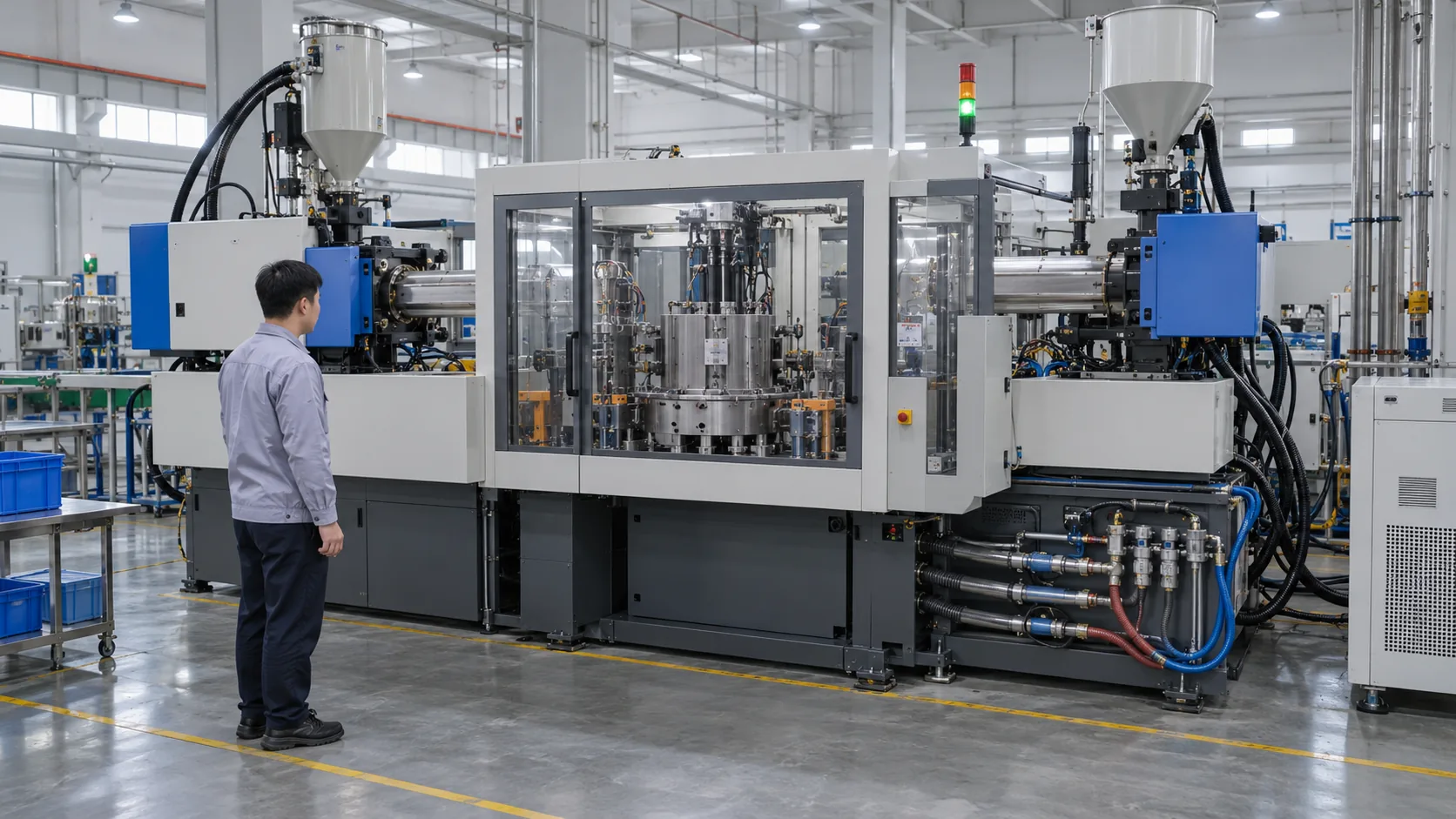
Production depends on sound sequence discipline. Mold rotation, core pulls, injection, cooling, and ejection need interlocks with clear timing. A jammed insert, incomplete index, or retained part can damage tooling if detection is weak.
Decision table: cell elements to review
| Cell element | Function | Review point |
|---|---|---|
| Injection unit A | Forms substrate | Shot size, residence time, and material preparation |
| Indexing system | Repositions substrate | Repeatability, support, and confirmation sensors |
| Injection unit B | Forms overmold region | Pressure, temperature, and gate location |
| Part detection | Confirms transfer and ejection | Fault response before mold closure |
Action recommendation: request a written cycle sequence and fault-recovery plan before approving cell architecture.
3. How do materials bond in a two-shot part?
Some polymer pairs form useful interfacial adhesion under suitable processing. Others need a mechanical interlock, undercut, hole, groove, or wrapped edge. Material trade names alone cannot settle compatibility because formulations, fillers, colorants, lubricants, and flame packages may alter behavior. A nominally compatible pair still needs testing under intended environmental loads.
- Compare supplier data for a specific grade pair.
- Keep substrate surfaces clean and free from release agents.
- Control melt, mold, and substrate temperatures.
- Design mechanical retention where bond loss creates risk.
- Test aged parts under heat, chemicals, moisture, and load.
Bonding lives at the interface. Component B must contact enough clean substrate area while carrying adequate heat and pressure. Excess delay, contamination, or poor venting can weaken an otherwise sensible material pair.
Decision table: bond controls and evidence
| Bond factor | Design or process control | Validation method |
|---|---|---|
| Grade compatibility | Use supplier-supported pairings | Molded peel, pull, or functional test |
| Surface condition | Prevent oil, dust, and release residue | Controlled handling and visual audit |
| Interface geometry | Add wraparound or interlocks where needed | Section review and destructive test |
| Service exposure | Match heat, fluid, UV, and load needs | Conditioned functional testing |
Action recommendation: freeze no material pair until representative molded coupons or parts pass relevant bond tests.
4. When is two-shot molding the right choice?
Two-shot becomes attractive when an integrated interface repeats across enough demand to offset dedicated tooling, cell setup, maintenance, and qualification. It also helps where hand placement would disturb a substrate or where consistent interface location matters. High demand alone does not settle a case; unstable product design can make dedicated two-component tooling an expensive trap.
- Part integration removes a joining or handling operation.
- Interface position needs close cycle-to-cycle repeatability.
- Product design and color plan are mature.
- Demand supports dedicated mold and machine time.
- Quality checks can verify both shots within one process flow.
Dedicated tooling creates a real commitment. Tool architecture links component geometries, cavities, cooling, and cycle balance. A late change on either material region may affect both stations.
Decision table: program fit for two-shot molding
| Program condition | Fit signal | Caution |
|---|---|---|
| Stable integrated design | Strong | Changes can affect both mold stations |
| Repeated hard-soft interface | Strong | Bond and shutoff still need proof |
| Low or uncertain demand | Weak | Dedicated tooling may remain underused |
| Frequent color or option changes | Conditional | Purging and inventory complexity may rise |
Action recommendation: model total process steps and change exposure before comparing only piece price.
5. How does transfer overmolding compare?
Transfer overmolding makes a polymer substrate, removes it, then places it into another cavity for added material. Transfer may happen by hand, robot, shuttle, or another machine. This route separates tooling and can accommodate bulky substrates or distinct thermal zones. It also introduces handling, orientation, storage, and contamination risks.
- Tool sets can change independently.
- Separate machines may absorb mismatched cycle times.
- Robots can add inspection between molding stages.
- Stored substrates need clean packaging and traceability.
- Cooling before transfer may alter adhesion behavior.
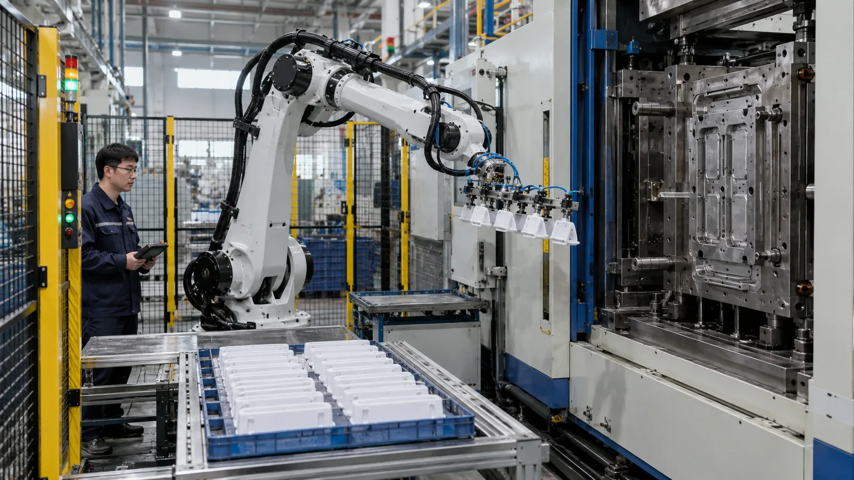
Flexibility carries a handling bill. Every transfer needs location control. Surface contamination, substrate distortion, wrong orientation, or mixed lots can appear between stages.
Decision table: two-shot versus transfer overmolding
| Criterion | Two-shot molding | Transfer overmolding |
|---|---|---|
| Substrate handling | Retained or indexed inside cell | Removed and reloaded |
| Tooling relationship | Closely integrated | More separable |
| Thermal condition | Often molded while warm | May cool before overmolding |
| Change flexibility | Lower for coupled geometry | Higher across separate tools |
| Handling risk | Lower transfer exposure | More orientation and contamination control |
Action recommendation: choose transfer overmolding when flexibility or substrate size outweighs added handling and control work.
6. When should you use insert molding?
Insert molding places a preformed item into a cavity, then injects polymer around selected areas. Inserts often include metal terminals, threaded hardware, bushings, pins, magnets, sensors, films, or previously made components. Unlike a typical two-shot substrate, an insert may come from another process or supplier.
- Incoming inserts need dimensional and surface controls.
- Placement requires reliable orientation and presence detection.
- Mold support must resist injection pressure and insert shift.
- Thermal expansion can create stress around large metal inserts.
- Knurls, grooves, holes, or flanges can improve retention.
Treat the insert as a supplied component. Its tolerance, cleanliness, plating, burrs, and storage history can influence molding results. Automation reduces manual variation only when feeding and detection remain dependable.
Decision table: insert conditions and process needs
| Insert condition | Process implication | Design check |
|---|---|---|
| Small metal terminal | Shift risk under flowing polymer | Support, gate direction, and detection |
| Threaded insert | Torque and pull-out loads | Retention geometry and test method |
| Large metal carrier | Thermal mismatch and stress | Preheat need, support, and cooling |
| Sensor or magnet | Damage and orientation risk | Temperature limit and poka-yoke |
Action recommendation: use insert molding when a supplied component must become captive within plastic and its incoming controls are manageable.
7. When does separate assembly make more sense?
Separate molding and assembly can outperform process integration when products need repair, late customization, material separation, or frequent revision. Parts may join through snaps, screws, ultrasonic welding, heat staking, adhesives, or another defined method. Assembly adds operations, yet those operations can provide useful decoupling.
- Different components can run on ordinary molding assets.
- Colors or options can be configured near shipment.
- Failed modules may remain replaceable.
- Incompatible materials can stay mechanically joined.
- Design changes may affect only one tool.
Extra steps can buy useful freedom. A replaceable seal or serviceable module may justify assembly labor. Recycling or disassembly goals may also favor reversible fasteners over permanent material integration.
Decision table: when assembly earns consideration
| Requirement | Molding implication | Assembly advantage |
|---|---|---|
| Field repair | Integrated part may be nonserviceable | Replace only failed component |
| Late color choice | Two-shot color lives in molding plan | Configure variants after molding |
| Weak material adhesion | Interfacial bond adds risk | Use fastener, weld, or designed lock |
| Unstable product design | Coupled tool changes become costly | Revise one component independently |
Action recommendation: retain assembly where service, customization, or design agility matters more than eliminating one downstream operation.
8. What design and tooling details control success?
Two-shot injection mold tooling starts with datum control. A warm substrate must remain located while component B pressure rises. Shutoff edges need enough land, support, and alignment to prevent flash without crushing component A. Gates should fill added regions without jetting across a visible surface or pushing unsupported geometry.
- Define which core or surface retains substrate location.
- Support thin substrate areas against injection pressure.
- Add venting near flow ends and trapped pockets.
- Keep shutoff edges accessible for fitting and maintenance.
- Account for shrinkage from both materials.
- Plan ejection around soft or easily marked areas.
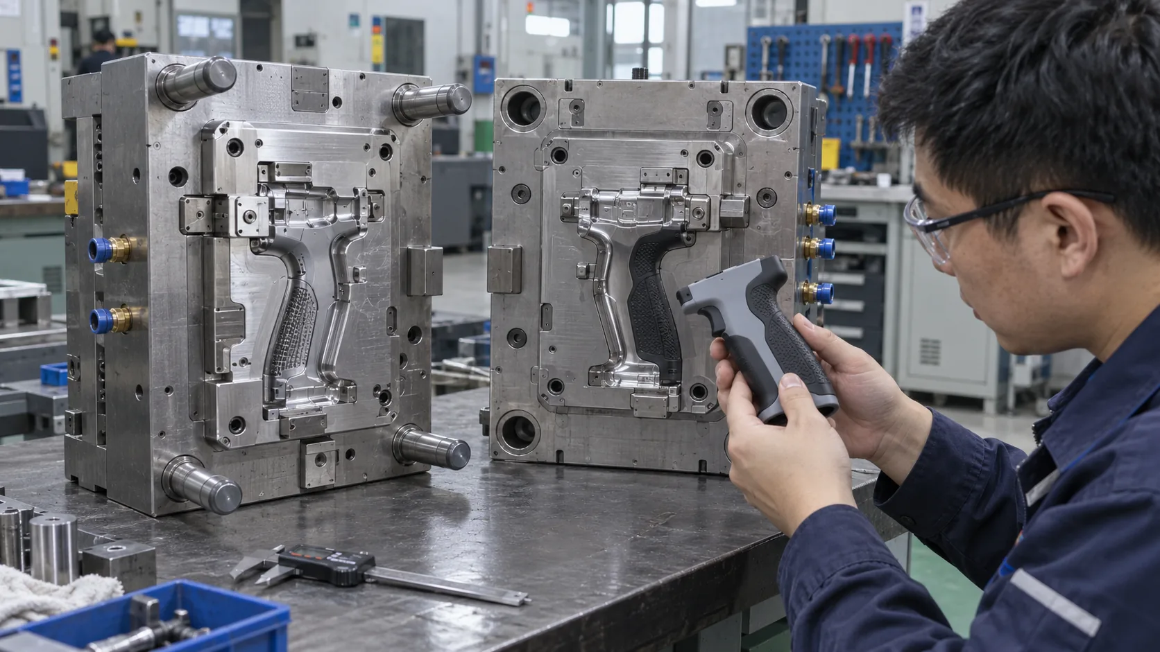
Tolerance stacks cross both stations. Variation in component A affects cavity space available for component B. That relationship should appear in dimensional plans, tool-steel conditions, and trial reports.
Decision table: design details and failure modes
| Feature | Likely failure mode | Review evidence |
|---|---|---|
| Substrate datum | Shift or uneven overmold | Datum scheme and transfer study |
| Shutoff land | Flash, crush, or witness variation | Section view and steel-safe plan |
| Gate location | Jetting, shift, or visible mark | Fill study or trial rationale |
| Venting | Burn, trapped gas, or weak interface | Vent map and cleaning access |
Action recommendation: review substrate location, shutoffs, gates, vents, and ejection as one linked system before tool release.
9. How should you evaluate a supplier and quotation?
A useful quotation states process architecture instead of saying “2K” alone. Ask which machine arrangement, mold-index method, injection-unit sizes, transfer controls, automation, and material-drying systems support your part. Tool scope should name cavity strategy, runners, shutoffs, inserts, sensors, spare strategy, and acceptance trials.
- Request a cycle sequence with station ownership.
- Ask for material-pair evidence and bond-test planning.
- Confirm shot size, platen space, tie-bar clearance, and clamp fit.
- Review fault detection for transfer, rotation, and ejection.
- Define dimensional, cosmetic, bond, and functional acceptance.
Equipment lists need project context. Our supplied company profile records three 160T two-color presses and two BabyPlast two-color units. Those facts show available platforms, but part fit still depends on mold size, shot demand, material, geometry, and required automation.
Decision table: quotation evidence to request
| Quotation item | Evidence expected | Hidden-risk warning |
|---|---|---|
| Machine selection | Unit sizes, clamp, platen, and mold fit | Tonnage stated without shot or space checks |
| Tool concept | Indexed sequence, runners, shutoffs, and cooling | Generic layout without substrate control |
| Material plan | Exact grades and bond-test method | Polymer families listed without grade pairing |
| Validation | Trial matrix and acceptance measurements | Sample approval based only on appearance |
Action recommendation: compare quotations on process scope and validation evidence before comparing price totals.
10. Which process should you choose for your part?
Choose two-shot molding when two molded components need repeatable integration and a stable program supports dedicated tooling. Choose transfer overmolding when separate tools, thermal separation, bulky substrates, or change flexibility outweigh added handling. Choose insert molding when polymer must capture a supplied metal, sensor, film, or preformed item. Choose assembly when service, late configuration, disassembly, or independent change has higher value.
- Identify every component and where it originates.
- State whether adhesion, sealing, retention, or appearance carries function.
- Estimate demand by variant rather than total family volume.
- Define environmental, dimensional, and bond tests.
- Share change expectations and service requirements.
Start with interfaces, not machine labels. A process becomes suitable only when it controls location, material behavior, function, quality evidence, and business change at acceptable risk.
Action recommendation: send suppliers a 3D model, exact material candidates, annual demand by variant, interface loads, cosmetic zones, test conditions, and assembly alternatives. Ask each supplier to explain why its proposed route beats remaining options for your part.
Frequently Asked Questions
Q1: Is two-shot molding the same as overmolding?
Two-shot molding is one form of overmolding. It usually keeps both injections within a coordinated cell, while transfer overmolding moves a molded substrate into another cavity or machine.
Q2: Can any two plastics bond in a two-shot process?
No universal grade compatibility exists. Bonding depends on exact grades, additives, temperature, surface condition, geometry, and processing. Use supplier guidance plus molded testing for a specific pair.
Q3: Does two-shot molding remove every assembly step?
Some downstream assembly may remain. A finished product can still need electronics, fasteners, decoration, inspection, or other modules.
Q4: Can two-shot molding use more than two materials?
Multi-component cells can use additional injection units and indexed positions. Complexity rises with every material, station, control loop, and tooling interaction.
Q5: What should an RFQ include?
Include 3D and 2D data, exact materials, demand by variant, interface functions, cosmetic requirements, tests, tolerances, target timing, and any preferred process route.