
What Tolerances Can Injection Molding Hold?
Injection molding tolerances depend on part size, resin, geometry, mold layout, processing, measurement conditions, and production evidence. A single universal number can mislead both buyer and supplier. Functional features may justify close control, while broad cosmetic or non-mating dimensions often permit wider limits. This guide shows how to specify tolerances that protect assembly and performance without loading an RFQ with avoidable cost.
1. What tolerances can injection molding hold?
No responsible answer starts with one blanket value. A small dimension near a well-packed gate behaves differently from a long distance across an asymmetric part. Semi-crystalline resin may respond differently from an amorphous grade. A flexible housing may also change shape between free-state inspection and clamped assembly.
Capability belongs to a defined feature. It also belongs to a material, cavity, process, sample condition, and measurement method.
Separate three questions before assigning limits:
- What variation can product function accept?
- What can proposed design and process feasibly produce?
- What can production data demonstrate under agreed conditions?
ISO 20457 provides a plastics-specific framework for geometrical and dimensional tolerances. It also warns against transferring metal-part assumptions directly onto molded plastics. Recommend using a standard as a negotiation framework, then approving critical values through part-specific evidence.
Which tolerance question are you answering?
| Question | Needed input | Correct output |
|---|---|---|
| Functional need | Assembly and performance limits | Required tolerance |
| Technical feasibility | Resin, geometry, mold, process | Proposed producible tolerance |
| Production capability | Stable trial or serial data | Demonstrated variation |
| Acceptance | Drawing and measurement agreement | Pass/fail decision rule |
2. Which tolerance types belong on a molded-part drawing?
Linear plus/minus dimensions cannot describe every functional relationship. Flatness can directly affect sealing performance. Position can control a screw boss relative to a datum system. Profile can manage a contoured mating surface. Perpendicularity may matter more than local width. A drawing should express function using a coherent datum strategy and suitable geometric controls.
Size alone rarely tells the whole fit story. A feature may meet diameter limits yet miss its mating location.
Review these specification types:
- linear size for widths, thicknesses, and diameters;
- form controls for flatness, straightness, or circularity;
- orientation and location controls tied to datums;
- profile where a complex surface carries functional meaning;
- surface, flash, parting-line, and appearance requirements stated separately.
ISO 1101 defines symbol language and interpretation rules for geometric specifications. Recommend asking a qualified drawing owner to remove duplicate controls and identify one datum scheme that matches assembly setup.
How should a feature be specified?
| Functional concern | Useful control type | Common mistake |
|---|---|---|
| Pin fits a hole | Size plus position | Tolerancing center distances independently |
| Cover seals on a rim | Profile or flatness | Controlling only local thickness |
| Boss stands square | Perpendicularity | Using a vague angular note |
| Cosmetic edge | Visual boundary and flash limit | Mixing appearance with dimensional size |
3. How do resin and shrinkage affect dimensional accuracy?
Resin behavior influences every dimensional forecast. Shrinkage can vary with flow direction, reinforcement, moisture, pressure, temperature, and section geometry. Supplier datasheets or standard specimens help compare materials, yet they cannot predict an exact production part with complex flow paths and uneven cooling.
A shrinkage value is an input, not an answer. Actual tooling and process conditions decide how that input appears in each feature.
Confirm these material details before tool sizing.
- exact grade, filler level, colorant, and approved substitute rules;
- shrinkage direction and test basis;
- moisture conditioning or post-mold change expectations;
- operating temperature and assembly restraint;
- recycled-content or lot-control requirements, where applicable.

ASTM D955 states that standardized shrinkage data cannot predict absolute values for actual parts with different flow paths, walls, gradients, and process conditions. Recommend freezing grade choice before final cavity compensation and validating critical dimensions through trial data.
Which material factors affect tolerance planning?
| Material factor | Dimensional effect | RFQ response |
|---|---|---|
| Flow-direction behavior | Different shrinkage by direction | Identify feature orientation |
| Reinforcement | Changes shrinkage and warpage pattern | Specify exact grade |
| Moisture response | Dimensions may shift after molding | Define conditioning state |
| Grade substitution | Changes processing and shrinkage | Require written approval |
4. How does part geometry change tolerance capability?
Geometry controls stiffness, flow, packing, cooling, and distortion. Uniform walls usually behave more predictably than abrupt thick-to-thin changes. Long unsupported panels can warp in free state. Deep ribs may pull nearby surfaces. Thick bosses can create local shrinkage or sink. Draft changes measured size along a feature's height.
The drawing can create its own variation. A tolerance attached to an unstable surface may fight material behavior rather than protect function.
Review geometry for:
- nominal wall consistency and thick local masses;
- flow length and gate access to critical regions;
- ribs, bosses, snaps, and metal inserts;
- asymmetric cooling or stiffness;
- measurement state for flexible or assembled parts.
Recommend tolerance reviews on section cuts and assembly models rather than isolated drawing callouts. Where function allows, control a stable interface or profile instead of many chained dimensions across deformable geometry.
Which geometry risks deserve attention?
| Geometry feature | Likely concern | Design response |
|---|---|---|
| Large flat panel | Free-state bow | Add stiffness or define restrained check |
| Thick boss | Local sink and shrinkage | Core or rebalance section thickness |
| Long dimension | Accumulated shrinkage variation | Tie control to function and datums |
| Deep drafted wall | Size changes with measurement height | Define measurement plane |
5. How do mold design and process control affect variation?
Precision mold engineering converts design intent into repeatable production. Gate location affects filling and packing. Cooling layout influences local shrinkage and warpage. Cavity balance matters in multi-cavity tools. Vents, ejection, inserts, and parting lines can alter local features. Process settings then operate within that hardware boundary.
Steel cannot rescue every callout. Some deviations require geometry changes, process work, or a revised measurement agreement.
Connect each critical feature with:
- gate and packing path;
- nearby cooling circuits and heat concentration;
- cavity identity in multi-cavity sampling;
- steel-safe correction strategy where practical;
- documented process window and material preparation.

Recommend reviewing critical dimensions on the tool concept before design release. Ask how adjustment remains possible after early trials, especially for shutoffs, mating locations, and features sensitive to warpage.
Which controls support dimensional stability?
| Control lever | Feature effect | Evidence to request |
|---|---|---|
| Gate location | Packing and orientation | Filling rationale or trial result |
| Cooling layout | Local shrinkage and warp | Circuit concept and temperature review |
| Cavity balance | Cavity-to-cavity variation | Identified cavity samples |
| Process window | Repeatability across runs | Approved settings and trial data |
6. How should molded parts be measured?
Measurement rules can change reported results, especially for flexible plastics. Fixture force may flatten a part. Datum setup can rotate it differently. Temperature, humidity, elapsed time after molding, and moisture conditioning may shift size. Instrument choice must fit feature geometry and required uncertainty.
A tolerance without a method invites argument. Supplier and buyer may both measure correctly under different setups yet report different values.
Define these items for critical checks:
- sample age, conditioning, and environmental state;
- datum simulation and fixture contact force;
- instrument, probe, scan, or gauge method;
- measurement location and section plane;
- repeated readings, cavity identity, and operator rules.
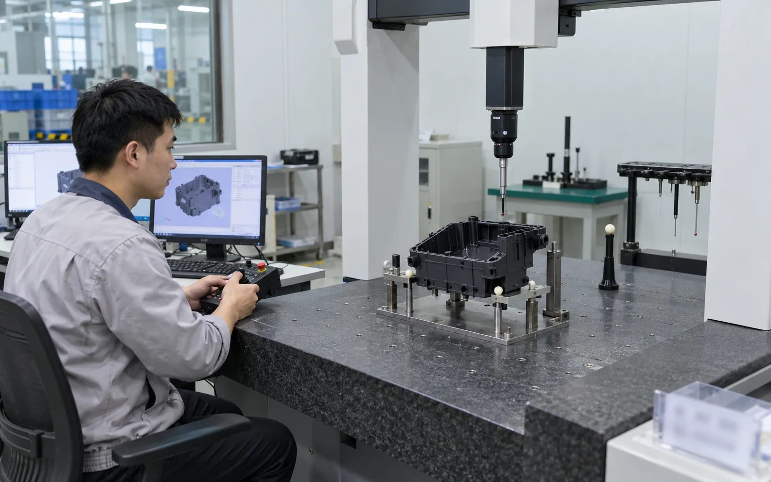
Recommend conducting a measurement-correlation exercise before rejecting early tooling samples. Compare setup, fixture, alignment, and calculation settings on the same identified parts.
What belongs in a measurement agreement?
| Measurement item | Why it matters | Agreement needed |
|---|---|---|
| Conditioning | Plastics may change after molding | Time, temperature, humidity |
| Datum fixture | Flexible parts can distort | Contacts, force, restraint |
| Instrument | Access and uncertainty differ | Gauge or CMM method |
| Data handling | Alignment changes calculated result | Software and reporting rule |
7. Why do tighter tolerances cost more?
Closer limits can require better tool adjustment, longer process development, added cooling time, more inspection, tighter material control, sorting, or cavity-specific correction. They can also increase scrap when natural process variation approaches specification limits. Cost rises fastest when many nonfunctional dimensions receive close limits.
Every close tolerance spends process margin. Use that margin where fit, sealing, motion, optics, noise, or safety gains a real benefit.
Classify drawing features into:
- function-critical characteristics with stated rationale;
- assembly interfaces needing controlled location or profile;
- process-monitoring dimensions that help detect drift;
- reference or low-risk dimensions needing wider general limits;
- cosmetic requirements controlled by boundary samples or visual criteria.
Recommend challenging each close tolerance with one question: what fails if this feature reaches either limit? Widen any value without a defensible functional consequence, subject to product-owner approval.
Where does tolerance cost appear?
| Requirement choice | Possible cost driver | Better question |
|---|---|---|
| Close limit everywhere | Inspection and scrap | Which features affect function? |
| Tight free-state flatness | Fixtures and correction loops | Does assembly restrain the part? |
| Close multi-cavity matching | Tool balancing and sampling | Must cavities be interchangeable? |
| Undefined cosmetic limit | Sorting and dispute | Can a boundary sample define acceptance? |
8. What tolerance information belongs in an RFQ?
A good RFQ identifies critical characteristics and explains their use. Suppliers need mating conditions, datum logic, resin grade, demand, cavity expectations, capability targets, and measurement rules. Without that context, bidders may assume different mold concepts or inspection loads.
Quote acceptance rules alongside part geometry. Commercial scope should include required samples, records, gauges, and repeat studies.
Send suppliers:
- controlled CAD and drawing revisions;
- critical-characteristic list with functional rationale;
- mating-part data or interface envelope;
- material grade and conditioning state;
- forecast, cavity strategy, sampling plan, and required capability evidence.
Recommend requiring a marked tolerance-feasibility response. Each bidder should classify critical values as accepted, conditionally accepted, or requiring design discussion before price closure.
Which RFQ inputs prevent false comparisons?
| RFQ input | Supplier decision affected | Buyer verification |
|---|---|---|
| Critical features | Tool adjustment and inspection | Link each feature with function |
| Measurement method | Gauge and labor scope | Define setup and sample state |
| Capability target | Trial and production evidence | Name index, sample, and conditions |
| Cavity plan | Output and variation study | Compare bids on equal cavity count |
9. How should tolerance capability be approved after tooling?
Tool approval should progress from correction samples toward production-representative evidence. Early trial parts help locate steel and process issues, though they may not represent serial material handling, cycle, automation, or cavity balance. Later studies should use an agreed process state and identified samples.
Conformance and capability answer different questions. One batch can fit limits while an unstable process remains risky.
Build approval stages around:
- drawing conformance on identified samples;
- cavity-to-cavity and run-to-run comparison;
- stable process conditions and material lot records;
- agreed sampling, data treatment, and capability method;
- action rules for centering, correction, or specification review.
NIST defines process capability as comparison between process performance and specification limits. Recommend calculating capability only after checking stability, sampling logic, and distribution assumptions. Never turn one index into an unconditional tolerance guarantee.
What should each approval stage prove?
| Stage | Main purpose | Release question |
|---|---|---|
| Early tool trial | Locate geometry and molding issues | What requires steel or process action? |
| Correction trial | Verify planned adjustments | Did targeted features move as expected? |
| Production-like run | Observe repeat variation | Are conditions representative and stable? |
| Ongoing production | Detect drift and changes | Do controls trigger action before escape? |
10. How can you set economical tolerances before tool approval?
Start with function, then work backward through assembly, datums, material behavior, geometry, mold strategy, process control, and measurement. Separate truly critical features from dimensions that only complete a drawing. A feasible tolerance still needs a clear acceptance method. A met limit still needs stable production evidence when capability matters. A mold validation and dimensional reporting guide can connect that evidence with tool approval.
Make every close callout earn its keep. This discipline protects both product performance and tooling budget.
Before tool approval:
- confirm one controlled drawing and datum scheme;
- freeze exact resin grade or substitution rules;
- review critical features against gate, cooling, and correction strategy;
- agree sample condition, fixture, instrument, and data method;
- define trial stages plus production capability evidence.
Recommend sending suppliers the drawing, CAD, resin grade, mating conditions, annual demand, and critical-feature rationale. Ask for a feature-by-feature feasibility response before approving steel.
Frequently Asked Questions
Q1: Is there a universal injection molding tolerance?
No universal figure applies across molded parts. Capability changes with feature size, resin, geometry, tool design, process, and measurement conditions. Use part-specific review and evidence.
Q2: Should every molded dimension use plus/minus tolerancing?
No single convention suits every functional feature. GD&T controls may express form, orientation, location, or profile more clearly with a coherent datum system.
Q3: Can a material shrinkage datasheet predict final part size?
It supports early planning, but actual dimensions also depend on flow path, walls, packing, cooling, mold design, and process conditions.
Q4: Does a capable process mean every future part will pass?
No capability study guarantees every future unit. Capability describes observed process performance against specifications under stated assumptions. Ongoing controls still need reaction rules for drift and change.
Q5: Can tolerances be corrected after tooling?
Some features allow steel-safe adjustment or insert replacement. Others require welding, remachining, process compromise, geometry revision, or a changed acceptance agreement.