
What Belongs on an Injection Mold Maintenance Checklist?
An injection mold maintenance checklist should turn visible condition and production history into controlled action. A calendar alone cannot do that. Resin, tool design, shot count, water quality, motion, storage, and defect trends change service demand. A useful checklist connects per-run observations with defined triggers, safe maintenance work, restart checks, and traceable records. It also follows mold-specific drawings plus equipment-manufacturer instructions.
1. What Should an Injection Mold Maintenance Checklist Control?
Build one system with several event points. Operators need start, run, and shutdown checks. Toolrooms need shot-count inspections, condition-triggered work, repair controls, storage preparation, and restart approval. Each task should name a responsible role, acceptance result, evidence field, and escalation route.
A checklist should drive a decision. “Inspect mold” provides little value unless a technician knows what to inspect and what result requires action. Keep observation and service work separate. Inspection can happen often, while disassembly, polishing, electrical testing, or component replacement needs trained personnel plus approved procedures.
Control these layers:
- Per-run observations before, during, and after molding
- Shot-count inspections based on mold history
- Condition triggers from parts, motion, leaks, or alarms
- Storage protection and controlled restart
- Records, approvals, open actions, and trend review
Action: Create a mold-specific checklist from drawings, manuals, resin history, and known wear points.
Checklist architecture
| Control layer | Trigger | Main output |
|---|---|---|
| Per-run | Setup, running, shutdown | Condition observation and escalation |
| Shot-count | Mold-specific accumulated cycles | Planned inspection or service |
| Condition | Defect, leak, motion change, alarm | Diagnosis and work order |
| Storage/restart | Tool removal or return | Protected storage and release record |
| History | Repeat event or overdue action | Revised task or trigger |
2. What Should Operators Check During Every Production Run?
Per-run checks catch changes before they become toolroom repairs. At startup, confirm mold identity, setup status, connections, guarding, and released process documentation. During production, watch parts and equipment for new evidence. Flash, drag marks, short shots, gate changes, ejector marks, unusual noise, water leakage, or rising scrap can signal several causes. Operators should record facts rather than diagnose by guesswork.
Production gives the earliest warning. Compare current parts with an approved sample and recent process history. A stable visual check needs cavity identification, defined defect limits, and a clear stop rule.
Include these run observations:
- Mold ID, machine, resin, setup, and cavity status
- Parting-line cleanliness plus visible damage
- Water, oil, air, or resin leakage
- Smooth opening, ejection, slide, and core-pull motion
- Part quality trend by cavity
- Shutdown condition and unresolved abnormalities
Action: Give operators a short run card with photo standards and one named escalation contact.
Per-run checkpoint
| Run stage | Observation | Escalate when |
|---|---|---|
| Startup | Identity, connections, guarding, baseline part | Setup differs from released record |
| Running | Leaks, motion, sound, part trend | New or worsening abnormality appears |
| Changeover | Resin, color, temperature, cleaning status | Change creates deposits or unstable parts |
| Shutdown | Tool condition, contamination, open issue | Mold cannot enter storage safely |
3. Which Conditions Should Trigger Maintenance?
Shot count gives a useful wear reference, but it cannot stand alone. An abrasive filled resin may change wear faster than an unfilled grade. Corrosive or outgassing materials can alter cleaning demand. Thin shutoffs, slides, lifters, valve gates, small vents, and high-temperature service also create specific risks. Cooling-water condition and storage humidity add more variables.
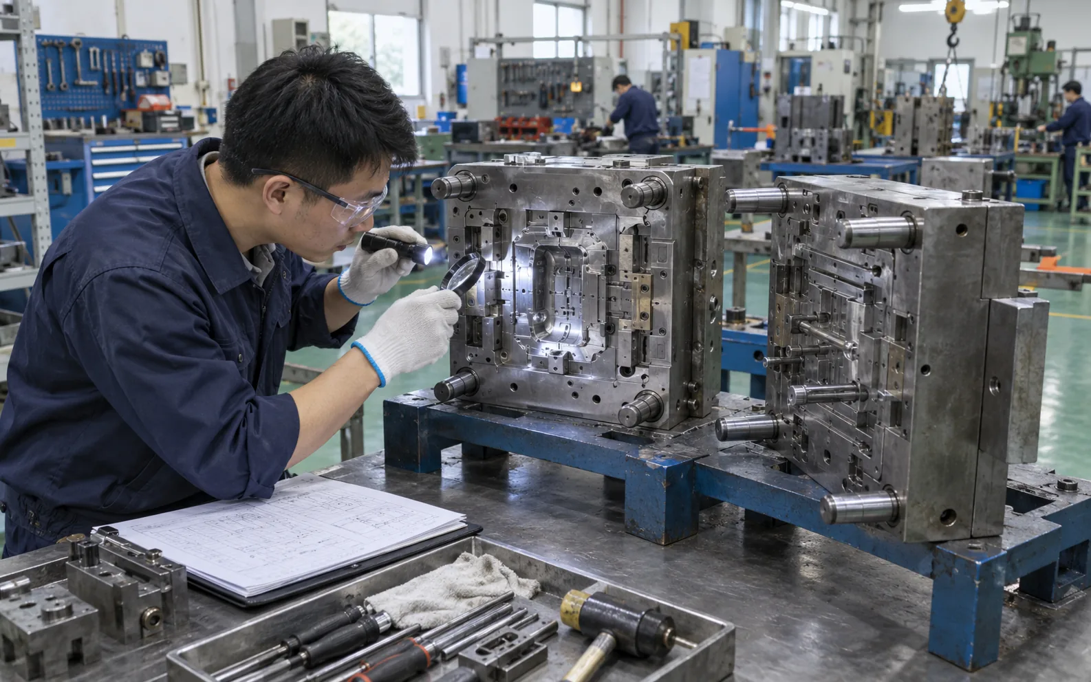
Let operating evidence set service frequency. Begin with builder and component-manufacturer guidance. Then adjust inspection points through actual mold history. Shorten a trigger after repeat findings. Extend it only through documented review, not convenience.
Use several trigger types:
- Accumulated shots or run hours
- Resin family, filler, pigment, or additive change
- Flash, sticking, burns, drag, imbalance, or scrap trend
- Leak, heater, thermocouple, motion, or sensor fault
- Extended idle period, transport, or storage exposure
- Repair, insert change, or engineering modification
Action: Set an initial trigger matrix and review it after each maintenance event.
Trigger-response checkpoint
| Trigger evidence | Immediate response | Planning response |
|---|---|---|
| Shot threshold reached | Inspect named wear points | Update finding history |
| Part defect trend | Contain output and verify cause | Revise inspection task if mold-related |
| Leak or abnormal motion | Stop under site rules | Open repair and root-cause record |
| Long idle period | Inspect protection and condition | Plan controlled restart |
4. How Should Cavities, Parting Lines, and Vents Be Cleaned?
Cleaning should remove residue without changing tool geometry or finish. Parting faces, precision shutoffs, vents, texture, polished cavities, and plated surfaces need different care. Use products approved for mold material, coating, resin residue, and later molding. Keep abrasive tools away from controlled edges unless an authorized repair process calls for them.
Clean does not mean polished everywhere. Overworking a vent or shutoff can create flash, trapped air, or fit loss. Technicians should record where buildup occurred because repeat deposits may point toward venting, resin, temperature, or process conditions.
Define these controls:
- Approved cleaner, cloth, brush, and hand-tool list
- Surface-specific method for texture, polish, coating, and shutoff
- Vent inspection criteria without casual re-cutting
- Debris capture and contamination prevention
- Before-and-after photos for abnormal findings
Action: Put cleaning limits and prohibited tools on each mold’s maintenance sheet.
Cleaning-control checkpoint
| Area | Inspect for | Control |
|---|---|---|
| Cavity/core | Deposit, stain, scratch, corrosion | Surface-approved cleaner and soft tool |
| Parting line | Resin, burr, dent, raised damage | Protect shutoff geometry |
| Vent | Deposit, blockage, damage | Clean without changing depth or width |
| Texture/polish | Uneven residue or marks | Use finish-specific method |
5. What Should Be Checked on Slides, Lifters, and Ejectors?
Moving components translate mold opening, hydraulic, pneumatic, or ejector motion into part release. Inspect contact patterns, travel, return, support, fasteners, wear plates, springs, pins, bushings, and sensors where fitted. New scoring, metal dust, galling, drag, delayed return, or uneven witness marks deserve investigation.
Control lubrication through mold-specific instructions. Product choice, amount, location, cleanliness, temperature, resin contact, and coating all matter. Excess grease can migrate onto parts or trap debris. Mixed lubricants may behave poorly. Follow builder drawings and component instructions.
Smooth motion must remain repeatable. Hand movement during service does not prove correct timing under production load.
Check these points:
- Full travel plus positive return
- Wear surfaces, guides, locks, and support plates
- Ejector straightness, return, and witness marks
- Sensor mounting, cable condition, and signal state
- Lubricant type, application point, and contamination
Action: Record measured wear or observed contact patterns instead of writing only “OK.”
Motion-component checkpoint
| Component | Evidence to record | Escalation example |
|---|---|---|
| Slide | Travel, contact, wear, lubrication | Scoring, loose gib, delayed return |
| Lifter | Tip fit, shaft wear, angle motion | Binding, chipped edge, part drag |
| Ejector | Straightness, return, surface mark | Sticking, breakage, uneven witness |
| Lock/sensor | Engagement, fastener, signal | Missed position or damaged cable |
6. What Belongs in a Cooling-Circuit Routine?
Cooling circuits affect mold temperature and production stability. A maintenance routine should identify every circuit, connection, plug, seal, baffle, bubbler, and manifold path. Check for external leakage, restricted flow, discolored discharge, deposits, corrosion evidence, damaged threads, and mixed connections.
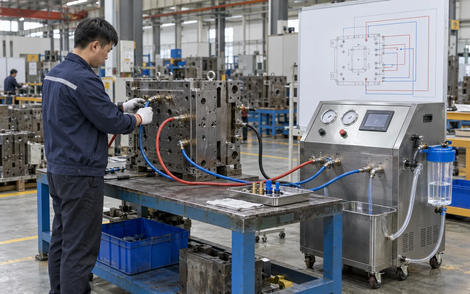
Flow evidence beats an open hose. Water leaving a port does not prove that each parallel path receives suitable flow. Use site-approved testing methods and compare results with a mold-specific baseline where available. Water treatment, temperature, material, and downtime influence deposit risk, so cleaning frequency should follow condition plus facility practice.
Include these circuit tasks:
- Verify circuit identity and connection map
- Inspect hoses, fittings, plugs, seals, and threads
- Check leak status and flow behavior
- Record deposits, corrosion, or contaminated discharge
- Drain, dry, or protect circuits before storage as specified
Action: Establish a baseline test after tool approval and compare later checks against that record.
Cooling-circuit checkpoint
| Check | Evidence | Response |
|---|---|---|
| External leak | Location and operating state | Repair before release |
| Flow change | Baseline comparison | Diagnose blockage, hose, or connection |
| Deposit/corrosion | Photo and discharge condition | Apply approved cleaning plan |
| Storage state | Drained, dried, capped, protected | Correct before storage |
7. How Do Hot Runners and Electrical Systems Change the Checklist?
Hot-runner work combines heat, electrical power, melt pressure, close fits, and manufacturer-specific assembly requirements. Qualified personnel should follow system manuals, drawings, torque values, temperature limits, and startup sequences. Generic instructions cannot replace those documents.
Checks may cover heater resistance, thermocouple response, connector condition, wiring insulation, and grounding. Further checks can cover leakage, valve-pin movement, actuation, and controller alarms. Test methods plus acceptable values must come from approved procedures.
Treat each system as its own asset. Record serial or configuration identity where available. A heater or thermocouple replacement should retain position, routing, and component specification.
Include these fields:
- System identity, drawing revision, and OEM procedure
- Heater, thermocouple, connector, and cable results
- Valve-pin or actuator condition where fitted
- Melt leakage, residue, and insulation condition
- Qualified technician, tools, torque, and test records
Action: Attach OEM service limits to checklist tasks and block unauthorized disassembly.
Hot-runner and electrical checkpoint
| Area | Check basis | Release evidence |
|---|---|---|
| Heater zone | OEM electrical method and limits | Recorded test result |
| Thermocouple | Response, polarity, placement | Stable reading by zone |
| Connector/wiring | Damage, routing, retention | Visual and electrical acceptance |
| Valve system | Temperature, motion, leakage | Function test under approved procedure |
8. What Should Storage and Restart Procedures Cover?
Storage begins before a mold leaves its machine. Record final part condition, unresolved issues, last shot count, and cleaning status. Remove residue, dry relevant surfaces, and protect steel with a compatible corrosion inhibitor. Then cap ports, secure loose items, support moving elements, and attach visible mold identity. Follow lifting plus storage rules for mold weight and configuration.
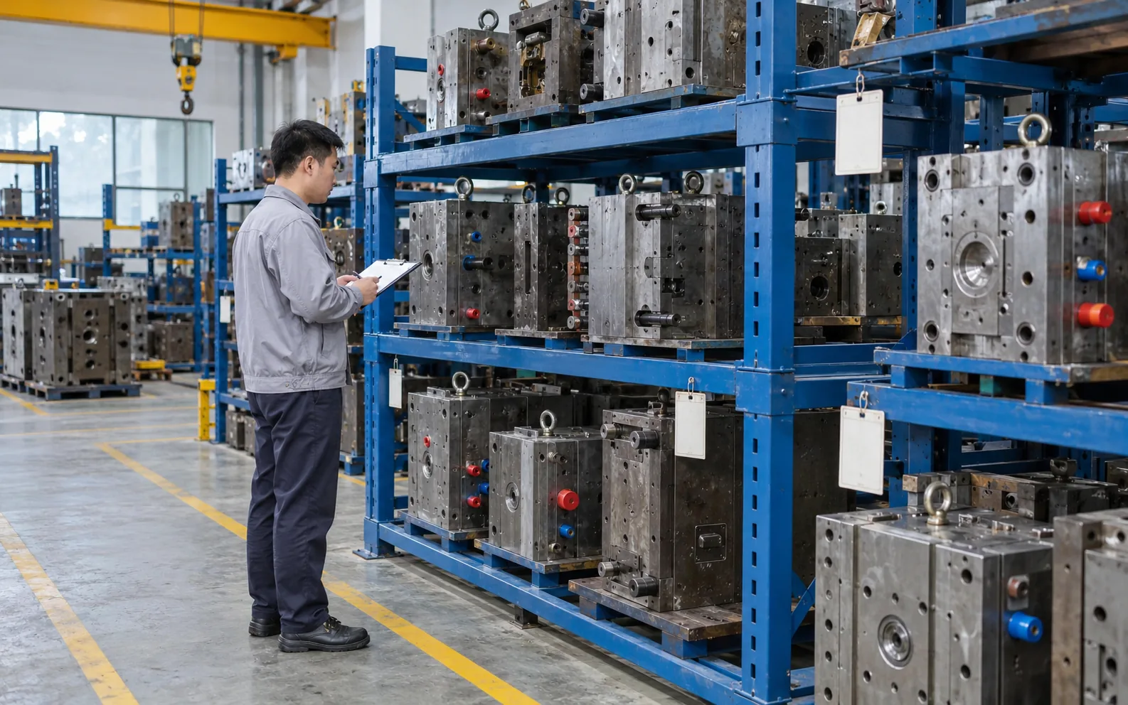
Restart should reverse storage deliberately. Inspect packaging and corrosion protection before cleaning. Check cavities, parting faces, motion components, circuits, wiring, connectors, fasteners, and safety devices. Remove preservative where required, reconnect against a map, and perform approved functional checks before saleable production.
Document these steps:
- Clean, dry, protected surfaces and circuits
- Capped connections, secured components, and mold ID
- Storage location, date, condition, and open work
- Restart inspection plus preservative removal
- Connection, motion, leak, heat, and sample approval
Action: Require a signed storage card and a separate restart release; one cannot substitute for another.
Storage-and-restart checkpoint
| Stage | Required state | Record |
|---|---|---|
| Removal | Condition captured and issues tagged | Last run and shot count |
| Preservation | Clean, dry, protected, capped | Product and application details |
| Storage | Supported, identified, location controlled | Date and owner |
| Restart | Inspected, connected, tested, sampled | Release signatures and findings |
9. Which Records Make Maintenance Decisions Repeatable?
Maintenance history should answer what changed, why work occurred, what technicians found, what they did, and whether production improved. A single “completed” checkbox cannot support that analysis. Tie every entry to mold ID, date, machine or bench state, accumulated shots, cavity, component, symptom, action, parts, and responsible person.
Use photos or measurements for wear, damage, corrosion, deposits, and repeated failures. Link repair records with trial results. Open actions need owners and due points. Trend reviews can reveal one cavity, connection, or motion component that consumes repeated attention.
Good records support better frequency decisions. Finding no wear across several controlled inspections may support a reviewed interval change. Repeat damage may require shorter checks, a design correction, process review, or operating change.
Capture these fields:
- Asset, revision, cavity, machine, resin, and shot count
- Trigger, symptom, defect, or alarm
- Inspection result, measurement, photo, and diagnosis
- Work performed, parts used, and technician
- Verification result, approver, next trigger, and open action
Action: Review recurring findings by mold and component, then update checklist tasks through formal approval.
Maintenance-record checkpoint
| Record field | Why it matters | Poor entry |
|---|---|---|
| Trigger | Explains why work started | “Routine” |
| Finding | Supports diagnosis and trend | “Checked” |
| Action | Shows exact work and parts | “Fixed” |
| Verification | Proves return condition | “Runs fine” |
| Next trigger | Controls future work | Blank date or shot count |
10. How Should Teams Assign Ownership and Escalation?
Operators monitor condition during production. Clear maintenance ownership in mass production should define who stops, services, verifies, and releases the mold. Setup technicians control installation and connections. Toolroom personnel inspect, service, and repair mold hardware. Process engineers assess molding conditions. Quality staff manage containment plus release evidence. Design or supplier engineering handles structural changes. Each site should map those roles onto its own safety and authorization system.
Ownership must stay visible at handoffs. Define who can stop production and open a work order. Also define who approves disassembly, accepts temporary repairs, and releases tooling after maintenance. Safety rules always override output pressure. Service that exposes workers to hazardous energy requires site procedures and applicable lockout controls.
Assign these decisions:
- Stop, contain, and notify
- Diagnose mold versus process evidence
- Authorize cleaning, disassembly, repair, or replacement
- Verify connections, motion, safety, and sample quality
- Approve return to service
- Revise tasks and triggers after review
Action: Pilot the checklist on one known mold, audit two complete run-maintenance-restart cycles, then release a controlled template.
Frequently Asked Questions
Q1: How often should an injection mold receive maintenance?
Use builder guidance, component manuals, shot history, resin, tool design, defects, water condition, and inspection findings. No single interval suits every mold.
Q2: Should shot count be the only preventive-maintenance trigger?
Shot count cannot stand alone. Combine it with condition signals, production events, material changes, storage exposure, and failure history.
Q3: Can operators clean a mold while it remains in the machine?
Only tasks covered by approved site procedures should occur there. Hazardous-energy exposure, guard removal, or entry into danger zones requires applicable safety controls.
Q4: What should happen before a mold enters long-term storage?
Record condition, clean and dry specified areas, protect steel, cap circuits, secure components, identify location, and note open work.
Q5: Who should release a mold after repair?
A defined authorized role should verify repair scope, connections, motion, safety checks, trial results, and quality evidence before production release.